


Page 8 - MS8200 / MS8300 Installation Manual
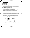
18-Pin Main Harness
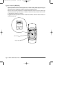
Pin 1 - BLACK: Ground.
Connect to a solid chassis ground. Be sure to use a ring connector of proper size. Scrape
away the paint at the grounding point.
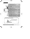
Pin 2 - YELLOW: Door Trigger (+12v) input
Connect to positive door switch circuit. This circuit, commonly found in Ford vehicles, will
show +12v when the door is open.
Pin 3 - WHITE/brown: Hood/Trunk Trigger (-) input
Connect to negative output from hood and/or trunk switches.
Pin 4 - YELLOW/violet: Auxiliary Function 3 (-) output
Provides a negative output to activate a relay. The output of this wire can be programmed
to operate in one of three operating modes. See
Programming
.
Momentary - provides output for as long as the transmitter button is pressed.
Latched - provides an output that stays active until the transmitter button is
pressed again.
Timed - provides an output that stays active for 30 seconds when the
transmitter button is pressed. If the transmitter button is pressed
again during the 30 seconds, the output will turn off.
Possible uses of the latched and timed outputs include: audio system valet, auxiliary lighting
control, timed headlight operation, etc.
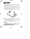
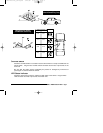
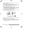
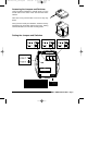
Pin 5 - BLUE: Starter Defeat Normally Closed (-) output
Provides a negative output while the alarm is Armed and during alarming to disable the
vehicle’s starter circuits. Connect to the provided Starter Kill Relay socket as shown.
In this configuration, the vehicle’s starter will be disabled only when the system is armed and
alarming. If power to the system is lost or the system becomes disconnected, the vehicle
will be able to start.
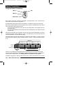
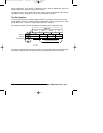
Wiring Description
RED
WHITE
to alarm
VIOLET wire
to alarm
BLUE wire
BLUE
to Starter
Solenoid
cut
to Ignition Key +12v
in “on” and “start”
VIOLET
installation_rev3.qxd 7/26/99 6:07 PM Page 8