


Page 10 - MS8200 / MS8300 Installation Manual
When latched or timed operation is selected, the output will reset (turn off) each time the
system is armed or disarmed.
Pin 15 - ORANGE/blue: Alarming / Horn Honk (-) output
Provides a negative output when the system is triggered to activate a relay. The output is
selectable for continuous or pulsed operation. See
Programming Switches
.
This wire can be connected to a relay to honk the vehicle’s horn, or activate an auxiliary
siren or air horns when the system is triggered.
Pin 16 - BLACK/white: Dome Light (+/-) output [on-board relay]
Illuminated Entry/Exit output. Provides a selectable positive (+12v) or negative (-) output to
turn on the vehicle’s dome light when the system is disarmed and when the ignition key is
turned off. Normally, this wire can be connected directly to the door switch circuit. Be sure
to set the polarity of this output. See
Jumper and Switch Settings
.
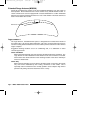
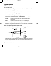
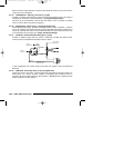
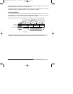
Pin 17 - BLUE/red: Starter Defeat Normally Open (-) output
Provides a negative output while the system is Disarmed to enable the starter circuits.
Connect to the provided Starter Kill Relay socket as shown.
In this configuration, the vehicle will only start when the system is both connected and
disarmed.
Pin 18 - RED/white: Secondary Power (+12v) input [20A fuse]
Connect to a fused +12v source. This wire is the source of power for all of the system’s on-
board relays, so a source of power capable of maintaining the necessary current is
essential. Be sure to install a fuse near the connection.
Do not
remove or bypass the fuse
holder included on the wire harness.
RED
BLACK
to alarm
VIOLET wire
to alarm
BLUE/red wire
to Starter
Solenoid
cut
VIOLET
to Ignition Key +12v
in “on” and “start”
BLUE
installation_rev3.qxd 7/26/99 6:07 PM Page 10