


MS8200 / MS8300 Installation Manual - Page 9
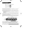
Pin 6 - WHITE: Door Trigger (-) input
Connect to negative door switch circuit. This circuit will show ground (-) when the door is
open.
Pin 7 - YELLOW/green: Auxiliary Function 4 (-) output
Provides a negative output to activate a relay. The wire provides output for as long as the
transmitter button is pressed.
Pin 8 - GRAY/black: Sensor Defeat (-) input
When this wire is grounded, the system will ignore the Logic Sensor II as well as any
additional sensors connected to the system’s Optional Sensor and Warn Away inputs. The
Sensor Defeat wire is normally used for defeating the sensors when an optional Remote Car
Starter is connected. When the car is started by remote, the Logic Sensor, ignition trigger,
and optional sensor inputs are ignored until after the remote starter is shut down.
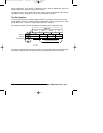
Pin 9 - YELLOW/white: Auxiliary Function 1 (+/-) output [on-board relay]
Provides selectable positive (+12v) or negative (-) output capable of activating a trunk
release solenoid. Output will stay on for as long as the Button is pressed.
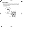
Pin 10 - RED: Main Power (+12v) input [3A fuse]
Connect to constant +12v. A clean source of power is essential. This connection can be
made at either the battery or at the constant power supply wire to the ignition switch. Be
sure to install a fuse near the connection.
Do not
remove or bypass the fuse holder
included on the wire harness.
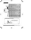
Pin 11 - ORANGE: Siren (+12v) output
Provides +12v to drive the siren. Connect to the Red siren wire. Connect the Black siren
wire to chassis ground.
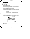
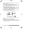
Pin 12 - RED/yellow: Parking Light (+/-) output [on-board relay]
Provides +12v or ground (-) to flash the parking lights. Do not connect this wire to parking
light circuits that exceed 10 amps. For vehicles that have independent left and right parking
light circuits, the parking light wires must be connected using diodes to keep the circuits
separate. See
Jumper Selections
to select polarity.
Pin 13 - VIOLET: Ignition input (+12v) input.
Connect to a source that maintains +12v when the ignition key is in both the "on" and "start"
positions.
Pin 14 - YELLOW/black: Auxiliary Function 2 (-) output. (resets with arm and disarm)
Provides a negative output to activate a relay. The output of this wire can be programmed
to operate in one of three operating modes. See
Programming
.
Momentary - provides output for as long as the transmitter button is pressed.
Latched - provides an output that stays active until the transmitter button is
pressed again.
Timed - provides an output that stays active for 30 seconds when the
transmitter button is pressed. If the transmitter button is pressed
again during the 30 seconds, the output will turn off.
Possible uses of the latched and timed outputs include: audio system valet, auxiliary lighting
control, timed headlight operation, etc.
installation_rev3.qxd 7/26/99 6:07 PM Page 9