


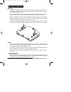
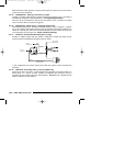
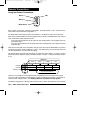

3-Pin Door Lock Harness
Pin 1 - WHITE/green: Door Lock (-) / Door Unlock (+)
Pin 2 - **not used**
Pin 3 - WHITE/blue: Door Unlock (-) / Door Lock (+)
These wires can be directly connected to negative and positive triggered door lock systems.
For Voltage Reversal systems and After-market actuators, add relays. For further
information, see
Door Lock Diagrams
. For selection of Double Pulse output, Comfort
Closure, and 4-second pulse, see
Programming
and
Jumper and Switch Settings
.
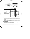
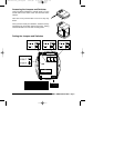
4-Pin Optional Sensor Harness
Pin 1 - RED: +12v output.
Provides +12v to power optional sensor. Do not connect this wire to anything other than an
optional sensor or the Space Shield III, included with the MS8300.
Pin 2 - WHITE
or
WHITE/orange: Armed (-) output.
Provides ground to turn on the optional sensor only when the system is Armed.
Pin 3 - WHITE/violet: Optional Sensor (-) trigger input.
Connect to the negative trigger output from an optional sensor.
Pin 4 - VIOLET/ yellow: Warn Away (-) input.
Connect to the negative Warn Away output from an optional sensor.
Other Harnesses
For details on the Status LED and Override Switch, see
Mounting Components
.
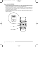
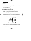
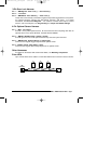
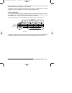
Extra LEDs
Up to 3 extra LEDs can be added. Cut the Red LED wire and connect in series as shown.
MS8200 / MS8300 Installation Manual - Page 11
LED
Connector
installation_rev3.qxd 7/26/99 6:07 PM Page 11