


Ungo Security Corporation
A Clarion Company
661 West Redondo Beach Blvd.
Gardena, CA 90247
800-Go-Clarion
www.clarionmultimedia
© Ungo Security Corporation, Gardena, CA 98-MS8200-00 Rev. 2 (12/97)
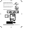
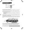
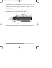
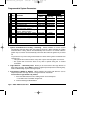
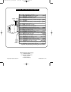
MS8200 / MS 8300 Wiring Diagram
Pin 4 - Violet/yellow: Warn Away (-) input
Pin 1 - Red: Sensor power +12v output
Pin 3 - White/violet: Optional Sensor (-) input
Pin 1 - White/green: Door Lock (-) / Unlock +12v output
[500mA]*
Pin 2 - White
or
White/Orange: Armed (-) output [150mA]
Pin 8 - Gray/black: Sensor Defeat (-) input
Pin 9 - Yellow/white: Auxiliary Function 1 (+/-) output
[built-in relay]
Pin 13 - Violet: Ignition Key +12v input
Pin 1 - Black: Chassis Ground
Pin 3 - White/blue: Door Unlock (-) / Lock +12v output
[500mA]*
Pin 14 - Yellow/black: Auxiliary Function 2 (-) output [500mA]
Pin 2 - **not used**
Pin 11 - Orange: Siren +12v output
[1 Amp]
Pin 17 - Blue/red: Starter Disable Normally Open (-) output [500mA]
Pin 18 - Red/white: Secondary Power +12v input [20A fuse]
Pin 15 - Orange/Blue: Alarming / Horn Honk (-) output [500mA]
Pin 2 - Yellow: Door Trigger +12v input
Pin 16 - Black/white: Dome Light (+/-) output
[built-in relay]
Pin 10 - Red: Main Power +12v input [3A fuse]
Pin 5 - Blue: Normally Closed Starter Disable (-) output [500mA]
Pin 4 - Yellow/violet: Auxiliary Function 3 (-) output [500mA]
Pin 3 - White/brown: Hood / Trunk (-) input
Pin 6 - White: Door Trigger (-) input
Pin 7 - Yellow/green: Auxiliary Function 4 (-) output
[500mA]
Logic
Sensor II
Override
Switch
Status
LED
Pin 12 - Red/Yellow: Parking Light (+/-) output
[built-in relay]
*for positive (+12v) polarity locking and unlocking max current is 150mA
installation_rev3.qxd 7/26/99 6:07 PM Page 28