


iv
T--298
LIST OF FIGURES
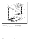
Figure 3-26 Cover Assembly - Low Profile 3-10.......................................................
Figure 3-27 Upper Scroll Assembly Locking Tabs (b.) & Screw Locations (c.) 3-10.........................
Figure 3-28 Upper Scroll Assembly Keeper Tab Release 3-10...........................................
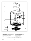
Figure 3-29 Upper Scroll & Control Box Cover Removed 3-11...........................................
Figure 3-30 Condenser Fan Assembly & Retaining Ring 3-11...........................................
Figure 3-31 Condenser Fan Motor & Fan Assembly Stop 3-11..........................................
Figure 3-32 Condenser Fan Motor & Fan Assembly Tab 3-11...........................................
Figure 3-33 Condenser Motor Ground 3-12...........................................................
Figure 3-34 Evaporator Motor Locking Tabs 3-12......................................................
Figure 3-35 Evaporator Motor/Blower Assembly In Cradle 3-12.........................................
Figure 3-36 Evaporator Blower Wheel (Flush With End Of Motor Shaft) 3-13..............................
Figure 3-37 Control Box Assembly With Capacitor 3-13................................................
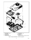
Figure 3-38 Remote Control Components 3-14........................................................
Figure 3-39 Remote Control PCB (FR9 Location) 3-14.................................................
Figure 3-40 Wall Thermostat Wiring Diagram - Cool Only Model 3-17....................................
Figure 3-41 Wall Thermostat Wiring Diagram - Heat/Cool Model 3- 18....................................
Figure 4-1 Upper Unit Schematic - Standard & HC 4-1................................................
Figure 4-2 Upper Unit Schematic - Low Profile 4-1...................................................
Figure 4-3 Ceiling Unit Schematic - Cooling Only 4-2.................................................
Figure 4-4 Ceiling Unit Schematic - Heat/Cool 4- 2....................................................
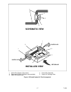
Figure 4-5 Ceiling Unit, Standard - Ducted 4-2.......................................................
Figure 4-6 Heat Pump - Upper Unit - Free Blow 4-3..................................................
Figure 4-7 Heat Pump - Ceiling Unit - Free Blow 4-3..................................................
Figure 4-8 Heat Pump - Upper Unit - Ducted 4-4.....................................................
Figure 4-9 Heat Pump - Ceiling Unit - Ducted 4-4....................................................
LIST OF TABLES
TABLE NUMBER Page
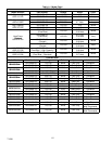
Table 1-1 Model Chart 1-2.........................................................................
Table 1-2 Additional Support Manuals 1-3............................................................
Table 2-1 System Self-diagnostics Function (Ducted Remote) 2-4.......................................