


T--298
3-6
3.5.2 Compressor Replacement
Observe the same procedures for rotary compressors
as for reciprocating compressors.
a. Follow all safety codes. Reminder: use protective
goggles, work gloves, and water soaked quenching
cloth.
b. Rem ove exterior cover. refer to paragraph 3.5.1. Dis-
connect a ll wiring from the compressor.
c. Apply field--supplied, line--tap--valves to the suction
and discharge lines as close to the compressor as
possible.
d. Recover therefrigerant charge from the unit. After re-
covering, cut the discharge and suction line process
tubes below the tube crimps. If you choose a good
tubing location for cutting the refrigeration lines ini-
tially, the location is easily accessible when making
the final joints.
WARNING
Oil vapor in piping stubs can ignite from
torch flame and cause serious injury. Exer-
cise extreme care when brazing, and keep
brazing cloth and fire extinguisher handy
for emergency use.
e. Connec t a nitrogen supply to the unit at one of the line
--tap--valve connectors (5--psig maximum flow), l eav-
ing the other connector open to the atmosphere.
Braze angle valves with stubs to each process tube.
f. Remove compressor from unit (3 bolts).
g. Rem ove line--tap--valves from suction and discharge
lines. C arefully braze the holes closedfrom where the
line--tap--valves were removed.
h. Cleansystem: addorreplace liquid linefilter drier. F or
proper cleaning and flushing use a UL approved re-
frigerant recycling system.
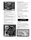
i. Install new compressor and braze into place with
field--supplied copper slip couplings.
j.Connect wiring: replace wire terminals if necessary.
k. Proceed with e vacuation and charging (15.9 OZ. --
.45 KG R22). Pinch off lines where angle valves were
added. Cut off angle valves above pinch--off , and
braze tubes.
l. Start up unit.
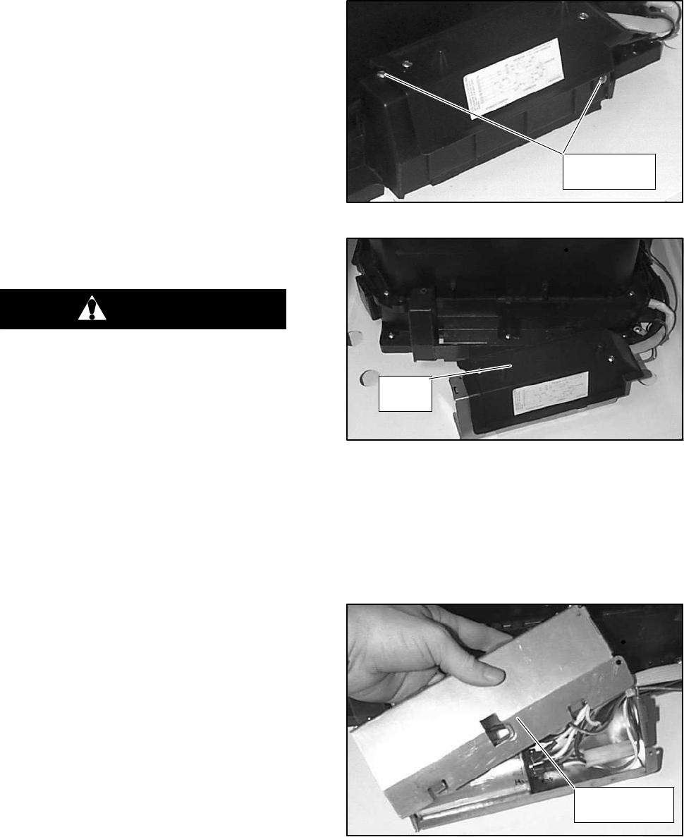
3.5.3 Control B ox Assembly Removal
To remove the control box assembly, do the following:
a. Rem ove exterior cover assembly. Refer to par agraph
3.5.1.
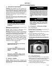
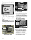
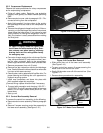
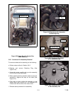
b. Rem ove 2 screws securing control box assembly to
the lower scroll assembly. (SeeFigure 3-15.)
Control Box
Screws
Figure 3-15 Control Box
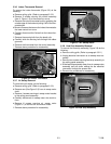
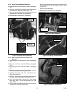
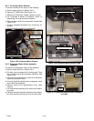
Water
Cover
Figure 3-16 Control Box Removal
c. Slide control box out of the lower scroll assembly.
(See Figure 3-16.)
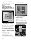
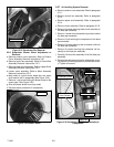
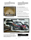
d. To open control box remove 2 screws securing the
water cover to the control box cover.
e. Gently lif t the water cover off of the control box. ( See
Figure 3-17.)
f. Reverse above procedure for reassembly.
Control Box
Cover
Figure 3-17 Water Cover Removal