


iii
T--298
TABLE OF CONTENTS - Continued
3.11 CHECK THERMOSTAT OPERATION 3-16...................................................
3.11.1 Temperature Display 3-16...............................................................
3.11.2 T imeguard Timer 3-17..................................................................
3.11.3 Cycle Timer 3-17......................................................................
3.11.4 Minimum On Timer 3-17................................................................
3.11.5 Error Messages 3-17...................................................................
WIRING SCHEMATICS 4-1........................................................................
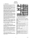
4.1 INTRODUCTION 4-1.....................................................................
LIST OF FIGURES
FIGURE NUMBER Page
Figure 1-1 Model/Serial Number Plate (Typical) 1-1...................................................
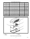
Figure 1-2 Roof Unit Component Identification 1-3....................................................
Figure 1-3 Ceiling Unit Component Identification (Free-Blow) 1-4.......................................
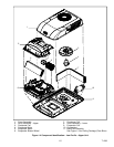
Figure 1-4 Component Identification - Low Profile - Upper Unit 1-5......................................
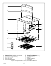
Figure 1-5 Component Listing-Ceiling Unit For Ducted Systems 1-6....................................
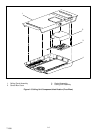
Figure 1-6 Ducted System Air Flow Arrangement 1-7.................................................
Figure 1-7 Serial Number Locations 1-8.............................................................
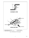
Figure 1-8 Refrigerant Flow Schematic (Standard System) 1-9.........................................
Figure 1-9 Refrigerant Flow Schematic - Heat Pump - (Cool Mode) 1-10.................................
Figure 1-10 Refrigerant Flow Schematic - Heat Pump - (Heat Mode) 1-11................................
Figure 3-1 Filter Removal - Free Blow 3-1...........................................................
Figure 3-2 Ceiling Grill - Free Blow 3-2..............................................................
Figure 3-3 Ceiling Panel Assembly 3-2..............................................................
Figure 3-4 Ceiling Panel With Heat Option 3-2.......................................................
Figure 3-5 Control Box Assembly - Free Blow 3-2....................................................
Figure 3-6 Indoor Thermostat 3-3..................................................................
Figure 3-7 Air sweep motor 3-3....................................................................
Figure 3-8 Heat Strip Assembly 3-3................................................................
Figure 3-9 Filter Removal - Ducted Unit 3-4.........................................................
Figure 3-10 Ceiling Grill - Ducted 3-4...............................................................
Figure 3-11 Control Box & PCB Cover 3-4...........................................................
Figure 3-12 Control Box Assembly - Ducted 3-5......................................................
Figure 3-13 Main/Display PCB’ s 3-5................................................................
Figure 3-14 Cover Assembly - Standard 3-5.........................................................
Figure 3-15 Control Box 3-6.......................................................................
Figure 3-16 Control Box Removal 3-6...............................................................
Figure 3-17 Water Cover Removal 3-6..............................................................
Figure 3-18 Upper Scroll Assembly 3-7.............................................................
Figure 3-19 Motor Assembly 3-7...................................................................
Figure 3-20 Spring Clamp Removal 3-7.............................................................
Figure 3-21 Motor Clip Removal 3-7................................................................
Figure 3-22 Condenser Fan Removal 3-8...........................................................
Figure 3-23 Blower Wheel 3-8.....................................................................
Figure 3-24 Condenser With Motor Assembly & Compressor 3-8.......................................
Figure 3-25 Set-Up For Discharging a Capacitor 3-9..................................................