


T--298
1-10
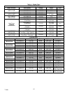
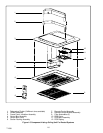
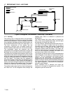
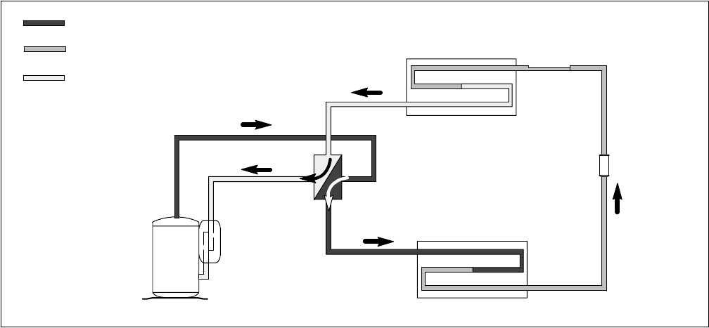
1.7 REFRIGERANT CYCLE -- HEAT PUMP
STRAINER
OUTDOOR COIL
INDOOR COIL
REVERSING VALVE
ACCUMULATOR
COMPRESSOR
CAPILLAR Y
TUBE
DISCHARGE
SUCTION
LIQUID
Figure 1-9 Refrigerant Flow Schematic -- Heat Pump -- (Cool Mode)
1.7.1 Cooling
The cooling cycle is energized when the thermostat,
located in the ceiling unit, calls for cooling The system
controls are positioned for “normal” refrigerant flow, with
the compressor discharge delivered to the outdoor coil
and liquid delivered to the indoor c oil. ( See Figure 1-9.)
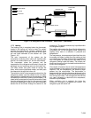
The main components of the system are the
compressor, reversing valve, air-cooled outdoor coil,
strainer, capillary tube, indoor coil, and the accumulator.
The compressor raises the pressure and the
temperature of the r efrigerant and forces it through the
discharge line and reversing valve into the outdoor coil.
The outdoor fan circulates surrounding air (which is at a
temperature lower than the refrigerant) over the outside
of the coil tubes. Heat transfer is established from the
refrigerant (inside the tubes) to the out door air (flowing
over the tubes). The tubes have fins designed to
improve the transfer of heat from the refrigerant gas to
the air; this removal of heat causes the refrigerant to
liquefy, thus liquid refrigerant leaves the coil and flows
through the strainer to the capillary tube. The strainer
removes any impurities within the refrigerant system.
The capillary tube meters the flow of liquid refrigerant to
the indoor coil. As the refrigerant flows through the
capillary tube, there is a reduction in pressure and
temperature.
The indoor blower (fan) pulls inside air through the
filters, which remove particulate matter, and then pass
the cleaned air through the indoor coil.
The low pressure, low temperature liquid that flows into
the indoor coil tubes is colder than the air that is
circulated over the tubes. H eat transfer is established
from the indoor air (flowing over the tubes) to the
refrigerant (flowing inside the tubes). The indoor coil
tubes have aluminum fins to increase heat transfer from
the air to the refrigerant; therefore the cooler air is
circulated to the interior of the vehicle.
The transfer o f heat from the air to the low temperature
liquid refrigerant in the indoor coil causes the liquid to
vaporize. This low temperature, low pressure vapor
passes into the accumulator. The accumulator is
designed wit h the inlet tube delivering refrigerant to t he
bottom of the tank and the outlet tube taking refrigerant
form the top of the tank. This arrangement ensures that
only vapor refrigerant is returned to the compressor,
where the cycle repeats.
When ventilation only is selected, the indoor fan
functions to circulate air throughout the vehicle. The
refrigerant cycle will remain off.