


T--298
3-4
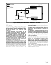
3.4 CEILING UNIT -- DUCTED SYSTEMS
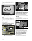
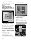
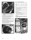
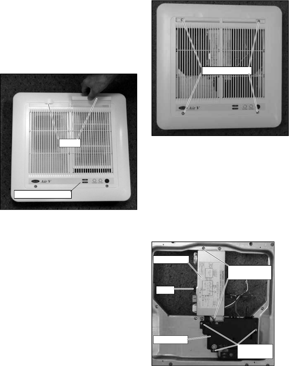
3.4.1 Filter Removal
The filters ( Figure 3-9) are loc ated in the ceiling grill. To
remove the filters, do the following:
a. Grasp the edge of the filter at recess in the end of the
ceiling grill.
b. P ull filter completely out of the filter slot.
c. Vacuum filter or wash filter in luke--warm water.
Shake off excess water and dry thoroughly.
d. Replac e filter by sliding the filter into the filter slot in
the ceiling grill until the filter frame is flush with t he in-
terior grill.
Filters
Operation Indicators
Figure 3-9 Filter Removal -- Ducted Unit
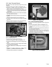
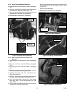
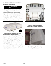
3.4.2 Ceiling Grill Removal
Toremove theceiling grill ( Figure 3--10) do thefollowing:
a. B efore working on unit place the master switch in the
OFF position and disconnect all electrical power.
b. Rem ove filters (Refer to paragraph 3.4.1).
c. Remove 4 screws located on the ceiling grill, (two are
under the filters) making sure to support the weight of
the grill.
d. Lower the ceiling grill from the ceiling panel.
e. To replace the gr ill, place the grill up against the c eil-
ing panel and align the screw holes in the grill with the
ceiling panel.
f. Replace 4 screws and 2 filters.
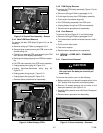
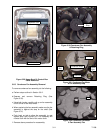
3.4.3 Control B ox Assembly Removal
To remove the control box assembly (Figure 3-11 &
Figure 3-12) do the following:
a. Rem ove ceiling grill. Refer to paragraph 3.4.2.
b. Dis connect 115 volt (AC) and 12 volt (DC) power
wires.
c. Remove two screws securing control box cover to
control box assembly. See Figure 3-11.
d. Remove control box assembly cover.
Mounting Screws
Figure 3-10 Ceiling Grill -- Ducted
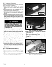
e. Dis connect blue furnace wires.
f. Unplug two connectors from upper unit.
g. Unplug DC power plug #1 (red/yellow/black wires)
SeeFigure3-12
h. Unplug r elay signal plug #2 (brown/red/orange/
yellow wires). See Figure 3-12
i. While supporting control box assembly remove two
screws securing control box assembly to ducted ceil-
ing unit.
j. Pullcontrolbox assembly from the ductedceilingunit.
k. Reverse above procedure to reassemble.
Control Box
PCB Cover
Fuse
Control Box
Cover Screws
PCB Cover
Screws
Figure 3-11 Control Box & PCB Cover