


T--298
3-17
3.1 1.2 Timeguard Timer
A 3--minute timeguard is built into the thermostat
immediately upon power up, and any time the
compressor (output “Y”) turns off. The compressor will
not turn on until the timeguard hasexpired. PressingUP
and FAN buttons simultaneously will override the
timeguard for 1 cycle.
3.1 1.3 Cycle Timer
In normal cooling (and heating) operation the
thermostat will not allow more than 4 equipment cycles
per hour (or 1 cycle every 15 minutes). Both the “Y”
(cooling) and “W” (heating) outputs have a 15--minute
timer that starts counting down when the output is
turned on, (e.g., if “Y” output is turned on for 9 m inutes
and then satisfies, it cannout turn back on for another 6
minutes regardless of demand). However, pressing UP
and FAN buttons simultaneously or changing the set
point will override the timer for 1 cycle.
3.11.4 Minimum On Timer
Once the equipment has turned on, it will remainon for a
minimum of 2 minutes regardless of demand. However,
the equipment can turn off in less than 2 minutes if a
change in set point, or a changein mode occurs.
3.1 1.5 Error Messages
E4 will be displayed if the thermostat has an internal
memory failure. If E4 appears, replace the thermostat.
---- (two dashes) will be displayed if the thermostat
cannot properly read the room temperature. If ----
appears, replace the thermostat.
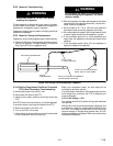
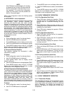
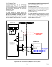
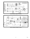
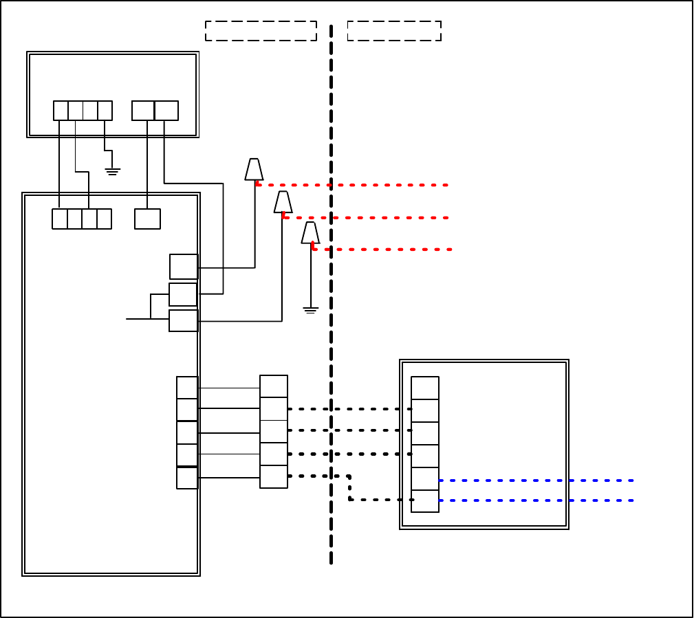
POWERBOX
ASSEMBLY
UPPER UNIT
1234 2
1
1234
1
2
3
4
5
L
N2
N1
W
Y
GH
GL
C
Y
GH
GL
R
C
COOL (Compressor)
FAN (High)
FAN (Low)
12VDC LowVoltage
Power Supply
CEILING UNIT
Motor Comp.
Factory Wiring Field Wiring
THERMOSTAT
J
115V AC High Voltage
Power Supply
Figure 3-40 Wall Thermostat Wiring Diagram -- Cool Only Model