


T--298
4-1
SECTION 4
WIRING SCHEMATICS
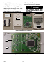
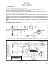
4.1 INTRODUCTION
This Section contains wiring schematics for the AirV units.
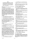
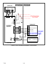
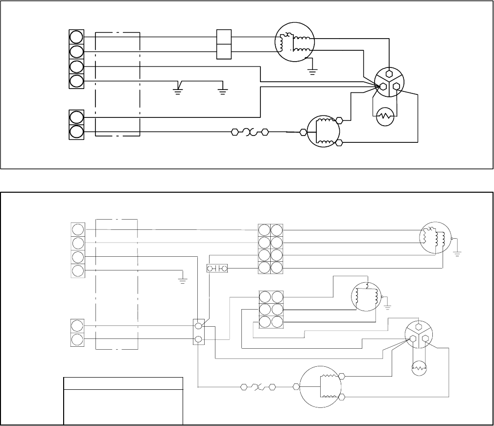
Figure 4--1 is the schematic for the standard upper unit assembly and it is applicable to all standard units.
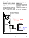
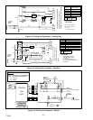
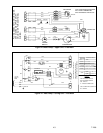
Figure 4--2 is the schematic for the Low Profile upper unit assembly.
Figure 4--3 is the schematic for a free blow ceiling unit without heat while Figure 4--4 is a free blow unit with heat.
Figure 4--5 is for a ducted unit with microprocessor control.
Figure 4--6 is for an Upper Unit Heat Pump with free blow application and Figure 4--7 is the matching free blow ceiling
unit.
Figure 4--8 is for the Upper Unit Heat Pump ducted application and Figure 4--9 is the matching ducted ceiling unit.
Note that the ducted units have 115 VAC power for the components and 12VDC power for the m icroprocessor c ontrol
system.
Figure 4--10 is for the duc ted or free blow application that uses a wall--mounted thermostat, with o r without the furnace
option.
Where applicable, diagrams that designate 115 V olt, 60 H, 1 Phase, are also available using 220 Volts, 50H, 1Phase.
Most noteably Figure 4--1 and Figure 4--5.
4P
2P
2P
C
F
H
1
11
22
3
4
2
BLK
BLU
BLK
BLU
WHT
WHT
GRN/YEL
CONTROL
BOX
EVAP.
GRN/YEL
GRN/YEL
WHT
BRN
1
2
CAPACITOR
YEL
YEL
RED
BLU
COMPRESSOR
R
C
S
FAN MOTOR
OVERLOAD PROTECTOR
RED
PTC
BLU
PLUG CONNECTS
TO CEILING UNIT
SEE FIG> 4--3
OR 4--4
(If Used)
Figure 4--1 Upper Unit Schematic -- Standard & HC
4P
2P
4P
C
F
H
BLK
BLU
BLK
BLU
WHT
GRN/YEL
GRN/YEL
WHT
WHT
WHT
BRN
BRN
1
(3)
2
CAPACITOR
YEL
RED
OLP
(IF USED)
BLU
BLURED
COMPRESSOR
R
C
S
1
2
3
4
1
2
1
2
3
4
1
2
3
4
OLP: OVERLOAD PROTECTION
PTC: START THERMISTER
JTB: JOINT TERMINAL BLOCK
FMC: INDOOR FAN MOTOR CAPACITOR
PLUG CONNECTS TO CEILING UNIT.
SEE DIAGRAM SUPPLIED WITH
CEILING UNIT FOR ADDITIONAL
WIRING.
INDOOR FAN MOTOR
YEL
WHT
YEL
1
2
3
1
2
3
WHT
3P
YEL
BRN
FMC
YEL
WHT
BRN
OUTDOOR FAN MOTOR
PTC
(IF USED)
LEGEND
(UNIT -- 99--00468--10)
Figure 4--2 Upper Unit Schematic -- Low Profile