


T--298
3-13
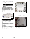
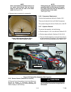
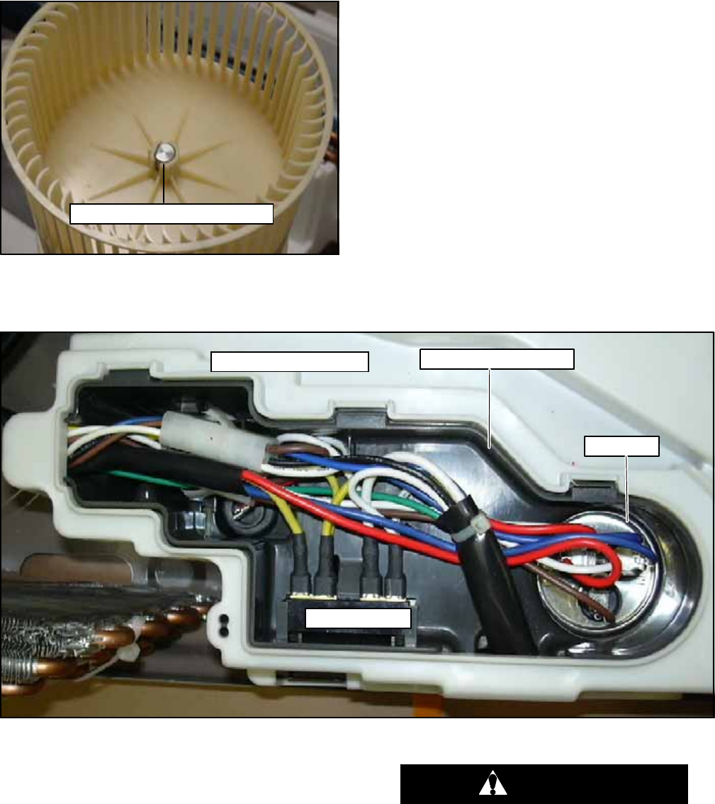
NOTE
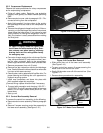
When reassemb ling the blower wheel on to
the motor shaft ensure that the blower
wheel is flush with the end of the motor
shaft (SeeFigure 3-36).
h. Rev erse above procedure for reassembly.
Wheel Flush With Motor Shaft
Figure 3-36 Evaporator Blower Wheel
(Flush With End Of Motor Shaft)
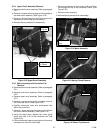
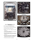
NOTE
When placing the evaporator motor/blower
assembly back into the l ower scroll assem-
bly cradle, make sure that the assembly is
seated securely in the cradle.
(See Figure 3-35).
3.6.6 Compressor Replacement
Perform the procedures outlined in Section 3.5.2
There are 4 bolts with the Low Profile Compressor.
The system charge for the Low Profile unit is 16.9 OZ.
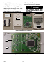
3.6.7 Capacitor Removal
To remove the capacitor, do the following:
a. P erform steps a., b. & c. as outlined in Section 3.6.5.
b. P erform steps outlined in Sections 3.5.8 & 3.5.9.
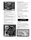
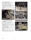
c. The Low Profile Capacitor is removed from the con-
trol box assembly by pushing on the capacitor from
under the control box assembly (See Figure 3-35).
Capacitor
Control Box Assembly
Terminal Block
Upper Scroll Assembly
Figure 3-37 Control Box Assembly With Capacitor
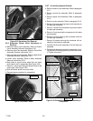
3.6.8 Remote Control (Fahrenheit to Celsius)
All Remote Control Assemblies in the United States are
pre--set to display in Fahrenheit degr ees (see
Figure 3-38). To change from a Fahrenheit display to a
Celsius display do the following:
CAUTION
The change from Fahrenheit to Celsius will
be permanent. It cannot bechanged backto
Fahrenheit.