


T--298
3-8
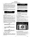
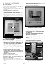
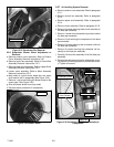
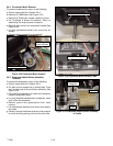
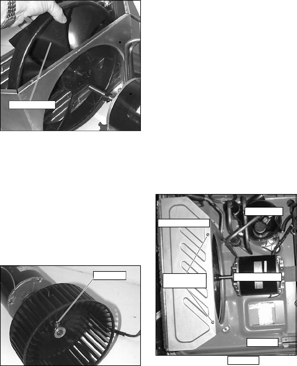
Condenser Fan
Figure 3-22 Condenser Fan Removal
3.5.6 Evaporator Blower Wheel Adjustment or
Removal
a. Rem ove exterior cover assembly. Refer to Exterior
Cover Assembly Removal instructions 3.5.1
b. Rem ove c ontrol box assembly. Refer to Control B ox
Assembly Removal instructions 3.5.3
c. Remove upper scroll assembly. Refer to Upper Scroll
Assembly Removal instructions 3.5.4
d. Loos en motor assembly. Refer to Motor Assembly
Removal instructions 3.5.5.
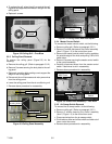
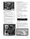
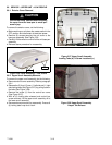
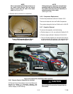
e. M ark shaft at a point where wheel hub and motor
shaft meet to aid in reassembly.(See Figure 3-23.)
f. Remove 1 set screw holding the blower wheel to the
motor shaft. (See Figure 3-23)
g. S lide of f blower wheel from motor shaft
h. Rev erse above procedure for reassembly.
Set Screw
Figure 3-23 Blower Wheel
3.5.7 Air Handling System Removal
a. Rem ove exterior cover assembly. Refer to par agraph
3.5.1.
b. Rem ove control box assembly. Refer to paragraph
3.5.3.
c. Remove upper scroll assembly. Refer to paragraph
3.5.4.
d. Rem ove motor assembly. Refer to paragraph 3.5.5.
e. Rem ove 8 screws securing lower scroll assembly to
the base pan assembly.
f. Remove 1 screw from clamp securing suction tube to
the base pan assembly.
g. Rem ove 3 nut s securing the compressor to the base
pan assembly.
h. Rem ove 2 screws securing the condenser orifice to
the base pan assembly.
i. Remove 2 screws securing the condenser coil as-
sembly to the base pan assembly.
j. Carefully lift the entire a ssembly off of the base pan
assembly.
k. Reverse the above procedure for reassembly, ensur-
ing that the air handling syst em is positioned correct-
ly. Tighten all screws.
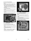
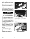
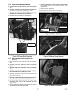
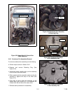
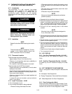
Condenser Cover
Condenser
Cover Screws
Compressor
Motor Assembly
Base Pan
Base Pan
Figure 3-24 Condenser With Motor Assembly &
Compressor