


7
S Masonry acid washing materials
All fuel-- burning equipment must be supplied with air for fuel
combustion. Sufficient air must be provided to avoid negative
pressure in the e quipment room or space. A positive seal must be
made between the furnace cabinet and the return--air duct to
prevent pulling air from the burner area and from draft safeguard
opening.
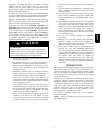
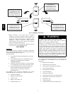
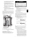
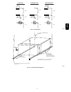
18-IN. (457.2 mm)
MINIMUM TO BURNERS
A93044
Fig. 5 -- Installa tion in a Garage
ELECTRICAL OPERATION HAZARD
Failure to follow this warning could result in personal
injury, death, and/or property damage.
When the furnace is installed in a residential garage, the
burners and ignition sources must be located at least 18
inches above the floor. The furnace must be located or
protected to avoid damage by vehicles. When the furnace is
installed in a public garage, airplane hangar, or other
building having a hazardous atmosphere, the furnace must
be installed in accordance with the NFGC or
CAN/CSA--B149.1--05. (See Fig. 5).
!
WARNING
PERSONAL INJURY AND/OR PROPERTY
DAMAGE HAZARD
Improper use or installation of this furnace may cause
premature furnace component failure.
This gas furnace may be used for heating buildings under
construction provided that:
--The furnace is permanently installed with all electrical
wiring, piping, venting and ducting installed according to
these installation instructions. A return air duct is provided,
sealed to the furnace casing, and terminated outside the
space containing the furnace. This prevents a negative
pressure condition as created by the circulating air blower,
causing a flame rollout and/or drawing combustion
products into the structure.
--The furnace is controlled by a thermostat. It may not be
“hot wired” to provide heat continuously to the structure
without thermostatic control.
--Clean outside air is provided for combustion. This is to
minimize the corrosive effects of adhesives, sealers and
other construction materials. It also prevents the
entrainment of drywall dust into combustion air, which can
cause fouling and plugging of furnace components.
--The temperature of the return air to the furnace is
maintained between 55_F(13_C) and 80_F(27_C), with
no evening setback or shutdown. The use of the furnace
while the structure is under construction is deemed to be
intermittent operation per our installation instructions.
--The air temperature r ise is within the rated rise range on
the furnace rating plate, and the gas input rate has been set
to the nameplate value.
--The filters used to clean the circulating air during the
construction process must be either changed or thoroughly
cleaned prior to occupancy .
--The furnace, ductwork and filters are cleaned as necessary
to remove drywall dust and construction debris from all
HVAC system components after construction is completed.
--Verify proper furnace operating conditions including
ignition, gas input rate, air temperature rise, and venting
according to these installation instructions.
CAUTION
!
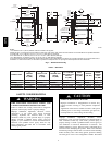
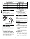
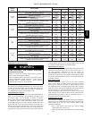
Table 2 – Minimum Free Area Required for Each Combustion Air Opening or Duct to Outdoors
FUR-
NACE
INPUT
(BTUH)
TWO HORIZONTAL DUCTS
(1 SQ. IN./2,000 BTUH)
(1,100 SQ. MM/KW)
SINGLE DUCT OR OPENING
(1 SQ. IN./3,000 BTUH)
(734 SQ. MM/KW)
TWO OPENINGS OR VERTICAL
DUCTS
(1 SQ. IN./4,000 BTUH)
(550 SQ. MM/KW)
Free Area of Opening
and Duct
(sq.in./sq.mm)
Round Duct
Diameter
(in./mm)
Free Area of Open-
ing and Duct
(sq.In./sq.mm)
Round Duct
Diameter
(in. / mm)
Free Area of
Opening and Duct
(sq.In./sq.mm)
Round Duct
Diameter
(In./mm)
44,000 22 (14193) 6 (152) 14.7 (9484) 5 (127) 11 (7097) 4 (102)
66,000 33 (21290) 7 (178) 22 (14193) 6 (152) 16.5 (10645) 5 (127)
88,000 44 (28387) 8 (203) 29.3 (18903) 7 (178) 22 (14193) 6 (152)
110,000 55 (35484) 9 (229) 36.7 (23677) 7 (178) 27.5 (17742) 6 (152)
132,000 66 (42581) 10 (254) 44 (28387) 8 (203) 33 (21290) 7 (178)
EXAMPLES: Determining F r ee Area
FURNACE WATER HEATER TOTAL INPUT
110,000 + 30,000 = (140,000 divided by 4,000) = 35.0 Sq. In. for each two Vertic al Ducts or Openings
66,000 + 40,000 = (106,000 divided by 3,000) = 35.3 Sq. In. for a Single Duct or Opening
88,000 + 30,000 = (118,000 divided by 2,000) = 59.0 Sq. In. for each of two Horizontal Ducts
58PHA