


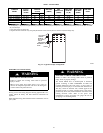
17
Return Air
Connections
FIRE HAZARD
Failure to follow this warning could cause personal injury,
death and/or property damage.
Never connect return--air ducts to the back of the furnace.
Follow instructions below
!
WARNING
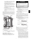
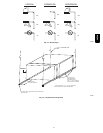
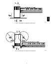
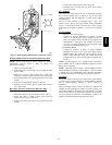
Downflow Furnaces
The return --air duct must be connected to return--air opening
(bottom inlet) as shown in Fig. 19. DO NOT cut into casing sides
(left or right). Side opening is permitted for only upflow and most
horizontal furnaces. (See Fig. 19.) Bypass humidifier connections
should be made at ductwork or coil casing sides exterior to
furnace.
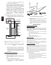
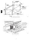
Upflow and Horizontal Furnaces
The return--air duct must be connected to bottom, sides (left or
right), or a combination of bottom and side(s) of main furnace
casing as shown in Fig. 18 and 20. Bypass humidifier may be
attached into unused return air side of the furnace casing. (See
Fig. 18 and 20.)
Not all horizontal furnaces are approved for side return air
connections. (See Fig. 20.)
GAS
PIPING
FIRE OR EXPLOSION HAZARD
Failure to follow this warning could result in personal
injury, death, and/or property damage.
Never purge a gas line into a combustion chamber. Never
test for gas leaks with an open flame. Use a commercially
available s oap solution made specifically for the detection
of leaks to check all connections.
!
WARNING
FIRE OR EXPLOSION HAZARD
Failure to follow this warning could result in personal
injury,death, and/or property damage.
Use proper length of pipe to avoid stress on gas control
manifold and a gas leak.
!
WARNING
FURNACE OVERHEAT HAZARD
Failure to follow this caution may result in property
damage.
Connect gas pipe to gas valve using a backup wrench to
avoid damaging gas controls and burner misalignment.
CAUTION
!
FIRE OR EXPLOSION HAZARD
Failure to follow this warning could result in personal
injury, death, and/or property damage.
If local codes allow the use of a flexible gas appliance
connector, always use a new listed connector. Do not use a
connector which has previously served another gas
appliance. Black iron pipe shall be installed at the furnace
gas control valve and extend a minimum of 2 in.(51 mm)
outside the furnace.
!
WARNING
Gas piping must be installed in accordance with national and
local codes. Refer to current edition of NFGC in the U.S., the
CAN/CSA--B149.1--05 in Canada.
Installations must be made in accordance with all authorities
having jurisdiction. If possible, the gas supply line should be a
separate line running directly from meter to furnace.
NOTE: In the state of Massachusetts:
1. Gas supply connections MUST be performed by a
licensed plumber or gas fitter.
2. When flexible connectors are used, the maximum length
shall not exceed 36 inches (915 mm).
3. When lever handle type manual equipment shutoff valves
are used, they shall be T--handle valves.
4. The use of copper tubing for gas piping is NOT approved
by the state of Massachusetts.
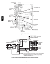
Refer to Tab le 6 for recommended gas pipe sizing. Risers must be
used to connect to furnace and to meter. Support all gas piping
with appropriate straps, hangers, etc. Use a minimum of 1 hanger
every 6 ft. (2 M). Joint compound (pipe dope) should be applied
sparingly and only to male threads of joints. Pipe dope must be
resistant to the action of propane gas.
An accessible manual e quipment shutoff valve MUST be
installed external to furnace casing and within 6 ft. (2 M) of
furnace. A 1/8--in. (3 mm) NPT plugged tapping, accessible for
test gauge connection, MUST be installed immediately upstream
of gas supply connection to furnace and downstream of manual
equipment shutoff valve.
NOTE: The furnace gas control valve inlet pressure tap
connection is suitable to use as test gauge connection providing
test pressure DOES NOT exceed maximum 0.5 psig (14--in. wc)
stated on gas control valve. (See Fig. 52.)
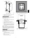
Some installations require gas entry on right side of furnace (as
viewed in upflow.) (See Fig. 21.)
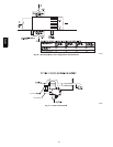
Install a sediment trap in riser leading to furnace as shown in Fig
22. Connect a capped nipple into lower end of tee. Capped nipple
should extend below level of furnace gas controls. Place a ground
joint union between furnace gas control valve and exterior
manual equipment gas shutoff valve. A 1/8--in. (3 mm) NPT
plugged tapping, accessible for test gauge connection, MUST be
installed immediately upstream of gas supply connection to
furnace and downstream of manual equipment shutoff valve.
58PHA