


22
FURNACE MAY NOT OPERATE
Failure to follow this caution may result in intermittent
furnace operation.
Furnace control must be grounded for proper operation or
else control will lock out. Control must remain grounded
through green/yellow wire routed to gas valve and manifold
bracket screw.
CAUTION
!
115--V WIRING
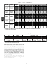
Verify that the voltage, frequency, and phase correspond to that
specified on unit rating plate. Also, check to be sure that service
provided by utility is sufficient to handle load imposed by this
equipment. Refer to rating plate or Table 7 for equipment
electrical specifications.
U.S. Installations: Make all electrical connections in accordance
with National Electrical Code (NEC) ANSI/NFPA 70--2008 and
any local codes or ordinances that might apply .
Canadian Installations: Make all electrical connections in
accordance with Canadian Electrical Code CSA C22.1 or
authorities having jurisdiction.
FIRE HAZARD
Failure to follow this warning could result in personal
injury, death, or property damage.
Do not connect aluminum wire between disconnect switch
and furnace. Use only copper wire.
!
WARNING
Use a separate, fused branch electrical circuit with a properly
sized fuse or circuit breaker for this furnace. See Table 7 for wire
size and fuse specifications. A readily accessible means of
electrical disconnect must be located within sight of the furnace.
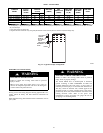
NOTE: Proper polarity must be maintained for 115--v wiring. If
polarity is incorrect, control LED status indicator light will flash
rapidly and furnace will NOT operate.
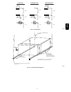
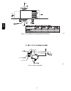
J --BOX RELOCA
TION
NOTE: If f actory location of J--Box is acceptable, go to next
section (ELECTRICAL CONNECTION TO J--BOX).
NOTE: On 14 --in. (356 mm) wide casing models, the J-- Box
shall not be relocated to other side of furnace casing when the
vent pipe is routed within the casing.
1. Remove and save two screws holding J--Box.
NOTE: The J--Box cover need not be removed from the J--Box
in order to move the J--Box. Do NOT remove green ground
screw inside J--Box. The ground screw is not threaded into the
casing flange and can be lifted out of the clearance hole in casing
while swinging the front edge of the J-- Box outboard of the
casing.
2. Cut wire tie on loop in furnace wires attached to J--box.
3. Move J--Box to desired location.
4. Fasten J--Box to casing with two screws removed in Step
1.
5. Route J--Box wires within furnace away from sharp edges,
rotating parts and hot surfaces.
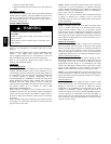
ELECTRICAL CONNECTION TO
J--BOX
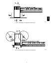
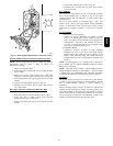
Field--Supplied Electrical Box on Furnace J --Box Bracket
See Fig. 23.
1. Remove cover from furnace J--Box.
2. Attach electrical box to furnace J--Box bracket with at least
two field--supplied screws through holes in electrical box
into holes in bracket. Use blunt--nose screws that will not
pierce wire insulation.
3. Route furnace power wires through holes in electrical box
and J--Box bracket, and make field--wire connections in
electrical box. Use best practices (NEC in U.S. and CSA
C22.1 in Canada) for wire bushings, strain relief, etc.
4. Route and secure field ground wire to green ground screw
on J--Box bracket.
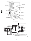
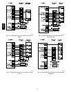
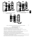
5. Connect line voltage leads as shown in Fig. 25.
6. Reinstall cover to J--Box. Do not pinch wires between
cover and bracket.
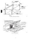
Electrical Box on Furnace Casing Side
See Fig. 23.
FIRE OR ELECTRICAL SHOCK HAZARD
Failure to follow this warning could result in personal
injury, death, or property damage.
If field--supplied manual disconnect switch is to be mounted
on furnace casing s ide, select a location where a drill or
fastener cannot damage electrical or gas components.
!
WARNING
1. Select and remove a hole knockout in the casing where the
electrical box is to be installed.
NOTE: Check that duct on s ide of furnace will not interfere with
installed electrical box.
2. Remove the desired electrical box hole knockout and
positionthe hole in the electrical box over the hole in the
furnace casing.
3. Fasten the electrical box to casing by driving two
fieldsupplied screws from inside electrical box into casing
steel.
4. Remove and save two screws holding J--Box. (See Fig.
22.)
5. Pull furnace power wires out of 1/2--in. (12 mm) diameter
hole in J-- Box. Do not loosen wires from strain--relief
wire--tie on outside of J--Box.
6. Route furnace power wires through holes in casing and
electrical box and into electrical box.
7. Pull field power wires into electrical box.
8. Remove cover from furnace J--Box.
9. Route field ground wire through holes in electrical box
and casing, and into furnace J--Box.
10. Reattach furnace J--Box to furnace casing with screws
removedinStep4.
11. Secure field ground wire to J--Box green ground screw.
12. Complete electrical box wiring and installation. Connect
line voltage leads as shown in Fig. 25. Use best practices
(NEC in U.S. and CSA C22.1 in Canada) for wire
bushings, strain relief, etc.
13. Reinstall cover to J--Box. Do not pinch wires between
cover and bracket.
58PHA