


37
The input rating for altitudes above 2,000 ft. (610 M) must
be reduced by 4 percent for each 1,000 ft. (305 M) above
sea level. For installations below 2000 ft. (610 M), refer to
the unit rating plate. For installations above 2000 ft. (610
M), multiply the input on the rating plate by the de--rate
multiplier in Table 8 for the correct i nput rate.
In Canada:
The input rating must be derated by 10 percent for
altitudes of 2,000 ft. (610 M) to 4,500 ft. (1372 M) above
sea level by an authorized Gas Conversion Station or
Dealer. To determine correct input rate for altitude, see
example 1 and use 0.90 as derate multiplier factor.
EXAMPLE 1:
88,000 BTUH INPUT FURNACE INSTALLED AT 4300
FT. (1310 M)
Furnace Input
Rate at Sea
Level
X Derate
Multiplier
Factor
0.90
= Furnace Input
Rate at
Installation
Altitude
88,000 X = 79,200
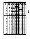
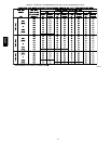
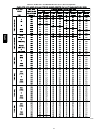
2. Determine the correct orifice and manifold pressure
adjustment. There are two different orifice and manifold
adjustment tables. All models in all positions, except Low
NOx models in downflow or horizontal positions, use
Table 13 (22,000 Btuh/Burner).
Low NOx models in the downflow or horizontal positions
must use Table 14 (21,000 Btuh/Burner). See input listed
on rating plate.
a. Obtain averageyearly gasheat value(atinstalledaltitude)
from local gas supplier.
b. Obtain average yearly gas specific gravity from local gas
supplier.
c. Find installation altitude in Table 13 or 14.
d. Find closest natural gas heat value and specific gravity
in Table 13 or 14.
e. Follow heat value and specific gravity lines to point of
intersection to find orifice size and manifold pressure
settings for proper operation.
f. Check and verify burner orifice size in furnace. NEVER
ASSUME ORIFICE SIZE. ALWAYS CHECK AND
VERIFY.
g. Replace orifice with correct size if required by Table 10,
12, 13, and 14. Use only factory --supplied orifices. See
EXAMPLE 2 .
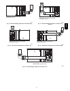
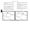
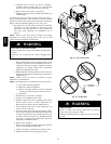
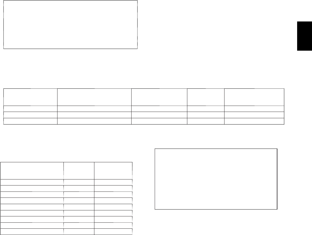
Caution!! For the following applications, use the minimum vertical vent heights as specified below. For all other applications,
follow exclusively the National Fuel Gas Code.
FURNACE
ORIENTATION
VENT ORIENTATION
FURNACE INPUT
(BTUH/HR)
MIN. VENT
DIAMETER
IN (MM)*
MIN. VERTICAL VENT
HEIGHT
FT.(M)**
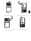
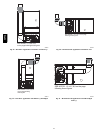
Downflow Vent elbow left, then up Fig. 38 132,000 5 (127 ) 12 (4)
Horizontal Left Vent elbow right, then up Fig. 41 132,000 5 (127 ) 7(2)
Horizontal Left Vent elbow right Fig. 42 132,000 5 (127 ) 7(2)
NOTE: All vent configurationsmust also meet National Fuel Gas Code ventingrequirementsNFGC
*4 in. (102 mm) inside casing or vent guard
**Including 4 in. (102 mm) vent section(s)
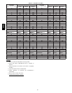
Table 10 – Altitude Derate Multiplier for U.S.A.
ALTITUDE
(FT. / M)
PERCENT
OF
DERATE
DERATE
MULTIPLIER
FACTOR*
0–2000 (0---610) 0 1.00
2001–3000 (610---914) 8–12 0.90
3001–4000 (914---1219) 12–16 0.86
4001–5000 (1219---1524) 16–20 0.82
5001–6000 (1524---1829) 20–24 0.78
6001–7000 (1829---2134) 24–28 0.74
7001–8000 (2134---2438) 28–32 0.70
8001–9000 (2438---2743) 32–36 0.66
9001–10,000 (2743---3048) 36–40 0.62
* Derate mul tiplier f actors are based on midpoint altitu de for altitude
range.
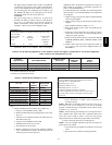
3. Adjust manifold pressure to obtain correct input rate.
a. Turn gas valve ON/OFF switch to OFF.
b. Removemanifoldpressuretapplug fromgasvalve. (See
Fig. 52.)
c. Connect a water column manometer or similar device to
manifold pressure tap.
d. Turn gas valve ON/OFF switch to ON.
e. Manually close blower door switch.
f. Set thermostat to call for heat.
g. Remove regulator seal cap and turn regulator adjusting
screw counterclockwise (out) to decrease input rate of
clockwise (in) to increase input rate.
EXAMPLE 2: (0 to 2000 ft. (0 to 610 M) altitude)
For 22,000 Btuh per burner application use Table 13.
Heating value = 1000 Btuh/cu ft.
Specific gravity = 0.62
Therefore: Orifice No. 43*
Manifold pressure: 3.7--in. wc
*Furnace is shipped with No. 43 orifices.
In this example all main burner orifices are the correct
size and do not need to be changed to obtain proper
input rate.
h. Install regulator seal cap.
i. Leave manometer or similar device connected and
proceed to Step 4.
NOTE: DO NOT set manifold pressure less than 3.2--in wc or
more than 3.8--in. wc for natural gas at sea level. If manifold
pressure is outside this range, change main burner orifices. Refer
to Table 10, 12, 13, and 14.
NOTE: If orifice hole appears damaged or it is suspected to have
been redrilled, check orifice hole with a numbered drill bit of
correct size. Never redrill an orifice. A burr--free and squarely
aligned orifice hole is essential for proper flame characteristics.
4. Verify natural gas input rate by clocking meter.
NOTE: Gas valve regulator adjustment cap must be in place for
proper input to be clocked.
a. Turn of f all other gas appliances and pilots served by the
meter.
b. Run furnace for 3 minutes in heating operation.
58PHA