


47
NOTE: The blower wheel should not be dropped or bent as
balance will be affected. The following steps should be performed
by a qualified service agency.
To ensure long life and high efficiency , clean accumulated dirt
and grease from blower wheel and motor annually.
The inducer and blower motors are pre--lubricated and require no
additional lubrication. These motors can be identified by the
absence of oil ports on each end of the motor.
Clean blower motor and wheel as follows:
1. Turn off electrical supply to furnace.
2. Loosen the thumbscrew on outer door and remove outer
door.
3. For downflow or horizontal furnaces having vent pipes
within the furnace that pass in front of the blower access
door:
a. Disconnect vent connector from furnace vent elbow.
b. Disconnect and remove short piece of vent pipe from
within furnace.
4. Remove two screws from blower access door and remove
blower access door.
5. Disconnect both harness connectors from blower motor
instead of at the circuit board. This reduces the chances of
a miswire when reconnecting wiring. The connectors are
polarized to prevent connection in the wrong orientation.
6. Remove two screws holding control box to blower shelf.
7. Hang control box from front of furnace casing and away
from blower compartment.
8. Remove two screws holding blower assembly to blower
deck and slide blower assembly out of furnace.
9. Clean blower wheel and motor using a vacuum with so ft
brush attachment. Blower wheel blades may be cleaned
with a small paint or flux brush. Do not remove or disturb
balance weights (clips) on blower wheel blades.
10. Vacuum any loose dust from blower housing, wheel and
motor.
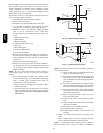
11. If a greasy residue is present on blower wheel, remove
wheel from the blower housing and wash it with an
appropriate degreaser. To remove wheel:
NOTE: Before disassembly, mark blower motor, and blower
housing so motor and each arm is positioned at the same location
during reassembly.
a. Disconnectpowerchokewires (ifused) and groundwire
attached to blower housing.
b. Remove screws securing cutoff plate and remove cutoff
plate from housing.
c. Loosen set screw holding blower wheel on motor shaft
(160+/ --20 in.--lb. when reassembling).
d. Removeboltsholding motorto blowerhousing and slide
motoroutofwheel(40+/--10in.--lb.whenreassembling).
e. Remove blower wheel from housing.
f. Clean wheel and housing.
12. Reassemble motor and blower by reversing steps 11f
through 11 a, finishing with 11a. Be sure to reattach
ground wire to the blower housing.
13. Verify that blower wheel is centered in blower housing
and set screw contacts the flat portion of the motor shaft.
Loosen set screw on blower wheel and reposition if
necessary.
14. Spin the blower wheel by hand to verify that the wheel
does not rub on the housing.
15. Reinstall blower assembly in furnace.
16. Reinstall control box assembly in furnace.
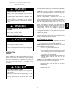
UNIT DAMAGE HAZARD
Failure to follow this caution may result in shortened heat
exchanger life.
Heating fan speed(s) MUST be adjusted to provide proper
air temperature rise as specified on the rating plate.
Recommended operation is at the midpoint of the rise range
or slightly above. Refer to “SET TEMPERATURE RISE”
under START --UP, ADJUSTMENT, and SAFETY
CHECK.
CAUTION
!
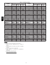
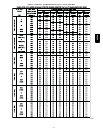
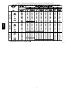
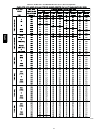
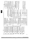
NOTE: Refer to Table 11 for motor speed lead relocation if
leads were not identified before disconnection.
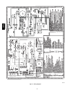
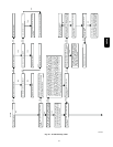
17. Reconnect blower leads to furnace control. Refer to
furnace wiring diagram, and connect thermostat leads if
previously disconnected.
18. To check blower for proper rotation:
a. Turn on electrical supply.
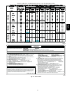
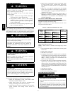
ELECTRICAL SHOCK HAZARD
Failure to follow this warning could result in personal
injury, or death.
Blower access door switch opens 115--v power to
furnace control. No component operation can occur
unless switch is closed. Exercise caution to avoid
electrical shock from exposed electrical components
when manually closing this switch for service purposes.
!
WARNING
b. Manually close blower access door switch.
NOTE: If thermostat terminals are jumpered at the time blower
access door switch is closed, blower will run for 90 sec before
beginning a heating or cooling cycle.
c. Perform component self-- test as shown at the bottom of
the SERVICE label, located on the frontof bloweraccess
door.
d. Verify blower is rotating in the correct direction.
19. If furnace is operating properly, RELEASE BLOWER
ACCESS DOOR SWITCH. Remove any jumpers or
reconnect any disconnected thermostat leads. Replace
blower access door.
20. Downflow or horizontal furnaces with vent pipe through
furnace only:
a. Installandconnectshort pieceof ventpipeinsidefurnace
to existing vent.
b. Connect vent connector to vent elbow.
21. Reinstall casing door.
22. Turn on gas supply and cycle furnace through one
complete heating and cooling cycle. Verify the furnace
temperature rise as shown in “Adjustments” Section.
Adjust temperature r ise as shown in “Adjustments”
Section. If outdoor temperature is below 70_F, (21_C)
turn off circuit breaker to outdoor unit before running
furnace in the cooling cycle. Turn outdoor circuit breaker
on after completing cooling cycle.
CLEANING HEAT
EXCHANGER
The following steps should be performed by a qualified
service agency:
NOTE: If the heat exchangers get a heavy accumulation of soot
and carbon, they should be replaced rather than trying to clean
58PHA