


43
SERVICE AND MAINTENANCE
PROCEDURES
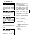
FIRE, INJURY, OR DEATH HAZARD
Failure to follow this warning could result in personal
injury, death and/or property damage.
The ability to properly perform maintenance on this
equipment requires certain knowledge, mechanical skills,
tools, and equipment. If you do not possess these, do not
attempt to perform any maintenance on this equipment
other than those procedures recommended in the User’s
Manual.
!
WARNING
ELECTRICAL SHOCK, FIRE OR EXPLOSION
HAZARD
Failure to follow this warning could result in personal
injury or death, or property damage.
Before servicing, disconnect all electrical power to furnace.
Verify proper operation after servicing.
!
WARNING
ELECTRICAL OPERATION HAZARD
Failure to follow this caution may result in improper
furnace operation or failure of furnace.
Label all wires prior to disconnection when servicing
controls. Wiring errors can cause improper and dangerous
operation.
CAUTION
!
INTRODUCTION
GENERAL
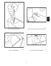
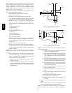
These instructions are written as if the furnace is installed in an
upflow application. An upflow furnace application is where the
blower is located below the combustion and controls section of
the furnace, and conditioned air is discharged upward. Since this
furnace can be installed in any of the 4 positions shown in Fig. 4,
you must revise your orientation to component location
accordingly.
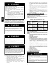
ELECTRICAL CONTROLS AND
WIRING
ELECTRICAL SHOCK HAZARD
Failure to follow this warning could result in personal
injury or death.
There may be more than one electrical supply to the
furnace. Check accessories and cooling unit for additional
electrical supplies that must be shut off during furnace
servicing.
CAUTION
!
The electrical ground and polarity for 115--v wiring must be
properly maintained. Refer to Fig. 25 for field wiring information
and to Fig. 59 for furnace wiring information.
NOTE: If the polarity is not correct, the STATUS LED on the
control will flash rapidly and prevent the furnace from heating.
The control system also requires an earth ground for proper
operation of the control and flame-- sensing electrode.
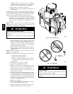
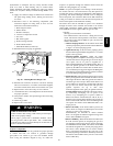
The 24 --v circuit contains an automotive--type, 3-- amp.. fuse
located on the control. (See Fig. 24.) Any shorts of the 24--v
wiring during installation, service, or maintenance will cause this
fuse to blow. If fuse replacement is required, use ONLY a 3--amp.
fuse. The control LED will display status code 24 when fuse
needs to be replaced.
Proper instrumentation is required to service electrical controls.
The control in this furnace is equipped with a Status Code LED
(Light--Emitting Diode) to aid in installation, servicing, and
troubleshooting. It can be viewed through the sight glass in
blower access door. The furnace control LED is either ON
continuously, rapid flashing, or a code composed of 2 digits. The
first digit is the number of short flashes, the second digit is the
number of long flashes.
For an e xplanation of status codes, refer to s ervice label located
on blower access door or Fig. 55 and the troubleshooting guide
which can be obtained from your distributor.
See Fig. 60, a brief Troubleshooting Guide.
For Controls With an Amber
LED
The stored status code will not be erased from the control
memory, if 115-- or 24--v power is interrupted.
1. To retrieve status code, proceed with the following:
NOTE: NO thermostat signal may be present at control, and all
blower--OFF delays must be completed.
a. Leave 115--v power to furnace turned on.
b. Remove outer access door.
c. Look into blower accessdoorsight glassforcurrentLED
status. Removing blower access door will open blower
access doorswitch andterminate115--v power tocontrol
so that status code is not displayed.
d. BRIEFLYremove insulated terminal wire from thedraft
safeguard (DSS) switch until LED goes out, then
reconnect it.
NOTE: If wire to LS or DSS is disconnected longer than 4 sec,
main blower starts, and retrieval request is ignored.
2. When above items have been completed, the LED flashes
status code 4 times. Record this status code for further
troubleshooting.
3. Check LED status. If no previous faults in history, control
will flash status code 11.
58PHA