


13
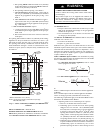
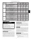
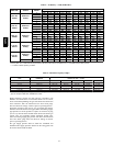
Table 4 – Opening Dimensions -- In. (mm)
FURNACE
CASING
WIDTH
APPLICATION
PLENUM OPENING FLOOR OPENING
A B C D
14–3/16
(360)
Upflow Applications on Combustible or Noncombustible Floor-
ing (KGASB subbase not required)
12---11/16
(322)
21---5/8
(549)
13---5/16
(338)
22---1/4
(565)
Downflow Applications on Noncombustible Flooring (KGASB
subbase not required)
12---9/16
(319)
19
(483)
13---3/16
(335)
19---5/8
(498)
Downflow applications on combustible flooring (KGASB sub-
base required)
11---13/16
(284)
19
(483)
13---7/16
(341)
20---5/8
(600)
Downflow Applications on Combustible Flooring with CNPV,
CNRV, CAR, or CAP Coil Assembly or KCAKC c oil box
(KGASB subbase not required)
12---5/16
(313)
19
(483)
13---5/16
(338)
20
(508)
17–1/2
(445)
Upflow Applications on Combustible or Noncombustible Floor-
ing (KGASB subbase not required)
16
(406)
21---5/8
(549)
16---5/8
(422)
22---1/4
(565)
Downflow Applications on Noncombustible Flooring (KGASB
subbase not required)
15---7/8
(403)
19
(483)
16---1/2
(419)
19---5/8
(498)
Downflow applications on combustible flooring (KGASB sub-
base required)
15---1/8
(384)
19
(483)
16---3/4
(425)
20---5/8
(600)
Downflow Applications on Combustible Flooring with CNPV,
CNRV, CAR, or CAP Coil Assembly or KCAKC c oil box
(KGASB subbase not required)
15---1/2
(394)
19
(483)
16---1/2
(419)
20
(508)
21
(533)
Upflow Applications on Combustible or Noncombustible Floor-
ing (KGASB subbase not required)
19---1/2
(495)
21---5/8
(549)
20---1/8
(511)
22---1/4
(565)
Downflow Applications on Noncombustible Flooring (KGASB
subbase not required)
19---3/8
(492)
19
(483)
20
(508)
19---5/8
(498)
Downflow applications on combustible flooring (KGASB sub-
base required)
18---5/8
(473)
19
(483)
20---1/4
(514)
20---5/8
(600)
Downflow Applications on Combustible Flooring with CNPV,
CNRV, CAR, or CAP Coil Assembly or KCAKC c oil box
(KGASB subbase not required)
19
(483)
19
(483)
20
(508)
20
(508)
24---1/2
(622)
Upflow Applications on Combustible or Noncombustible Floor-
ing (KGASB subbase not required)
23
(584)
21---1/8
(537)
23---5/8
(600)
22---1/4
(565)
Downflow Applications on Noncombustible Flooring (KGASB
subbase not required)
22---7/8
(581)
19
(483)
23---1/2
(597)
19---5/8
(498)
Downflow applications on Combustible flooring (KGASB sub-
base required)
22---1/8
(562)
19
(483)
23---3/4
(603)
20---5/8
(600)
Downflow Applications on Combustible Flooring with CNPV,
CNRV, CAR, or CAP Coil Assembly or KCAKC c oil box
(KGASB subbase not required)
22---1/2
(572)
19
(483)
23---1/2
(597)
20
(508)
HORIZONTAL INSTALLATION
FIRE, EXPLOSION, AND CARBON MONOXIDE
POISONING HAZARD
Failure to follow this warning could result in personal
injury, death, and/or property damage.
Do not install the furnace on its back or hang furnace with
control compartment facing downward. Safety control
operation will be adversely af fected. Never connect
return--air ducts to the back of the furnace.
!
WARNING
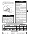
The furnace can be installed horizontally in an attic or crawl space
on either the left--hand (LH) or right --hand (RH) side. The furnace
can be hung from floor joists, rafters or trusses or installed on a
non--combustible platform, blocks, bricks or pad.
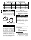
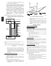
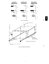
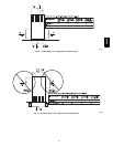
Suspended Furnace
Support
The furnace may be supported under each end with threaded rod,
angle iron or metal plumber’s strap as shown. (See Fig. 15 and
16.) Secure angle iron to bottom of furnace as shown.
Heavy--gauge sheet metal straps (plumber’ s straps) may be used
to suspend the furnace from each bottom corner. To prevent
screws from pulling out, use 2 #8 x 3/4--in. (19 mm) screws into
the side and 2 #8 x 3/4--in. (19 mm) screws in the bottom of the
furnace casing for each strap. (See Fig. 15 and 16.) If the screws
are attached to ONLY the furnace sides and not the bottom, the
straps must be vertical against the furnace sides and not pull away
from the furnace sides, so that the s trap attachment screws are not
in tension (are loaded in shear) for reliable support.
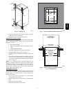
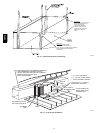
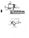
Platform Furnace
Support
Construct working platform at location where all required furnace
clearances are met. (See Fig. 2 and 17.) For furnaces with 1--in.
(25 mm) clearance requirement on side, set furnace on
noncombustible blocks, bricks or angle iron. For crawl space
installations, if the furnace is not suspended from the floor joists,
the ground underneath furnace must be level and the furnace set
on blocks or bricks.
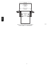
Roll--Out Pr
otection
Provide a min imum 17--3/4 in. x 22 in. (451 mm x 559 mm)
piece of sheet metal for flame roll--out protection in front of
burner area for furnaces closer than 12 inches (305 mm) above
the combustible deck or suspended furnaces closer than 12 inches
(305 mm) to joists. The sheet metal MUST extend underneath the
furnace casing by 1 in. (25 mm) with the door removed.
The bottom closure panel on furnaces of widths 17--1/2 in. (445
mm) and larger may be used for flame roll--out protection when
bottom of furnace is used for return air connection. See Fig. 17
for proper orientation of roll--out shield.
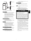
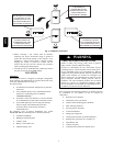
Bottom Return Air
Inlet
These furnaces are shipped with bottom closure panel installed in
bottom return--air opening. Remove and discard this panel when
bottom return air is used. To remove bottom closure panel,
perform the following:
1. Tilt or raise furnace and remove two screws holding
bottom filler panel. (See Fig. 9.)
2. Rotate bottom filler panel downward to release holding
tabs.
58PHA