


39
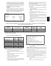
Table 11 – Speed Selection
COLOR SPEED AS SHIPPED
Gray 5 COOL
Yellow 4 SPARE
Blue 3 HEAT
Orange 2 SPARE
Red 1* CONT FAN
* Continuous ---blower speed ---as shipped default
FURNACE OVERHEATING HAZARD
Failure to follow this caution may result in reduced furnace
life.
Recheck temperature rise. It must be within limits specified
on the rating plate. Recommended operation is at the
mid--point of rise range or slightly above.
CAUTION
!
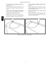
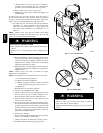
6. Set thermostat heat anticipator.
a. Mechanical thermostat -- Set thermostat heat anticipator
to match the amp. draw of the electrical components in
the R--W circuit. Accurate amp. draw readings can be
obtained at the wires normally connected to thermostat
subbase terminals, R and W. The thermostat anticipator
should NOT be in the circuit while measuring current.
(1.) Remove thermostat from subbase or from wall.
(2.) Connect an amp. meter as shown in Fig. 54 across
theR and W subbase terminalsor R and W wires at
wall.
(3.) Record amp. draw across terminals when furnace is
in heating and after blower starts.
(4.) Set heat anticipator on thermostat per thermostat
instructions and install on subbase or wall.
b. Electronic thermostat: Set cycle rate for 4 cycles per hr.
7. Adjust blower off delay The blower off delay has 4
adjustable settings from 90 sec to 180 sec. The blower off
delay jumpers are located on the furnace control board.
(See Fig. 24.)
To change the blower off delay setting, move the jumper
from one set of pins on the control to the pins used for the
selected blower off delay. Factory off delay setting is 120
sec.
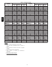
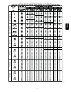
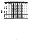
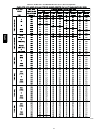
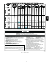
8. Set airflow CFM for cooling
Select the desired blower motor speed lead for cooling
airflow. See Table 5--Air Delivery--CFM (With Filter). See
Table 11 for lead color identification.
Check Safety Contr
ols
The flame sensor, gas valve, and pressure switch were all checked
in the Start--up procedure section as part of normal operation.
1. Check Main Limit Switch(es)
This control shuts off combustion control system and
energizes air--circulating blower motor, if furnace
overheats. By using this method to check limit control, it
can be established that limit is functioning properly and
will operate if there is a restricted duct system or motor
failure. If limit control does not function during this test,
cause must be determined and corrected.
a. Run furnace for at least 5 minutes.
b. Gradually block off return air with a piece of cardboard
or sheet metal until the limit trips.
c. Unblock return air to permit normal circulation.
d. Burners will re--light when furnace cools down.
2. Check draft safeguard switch.
The purpose of this control is to cause the safe shutdown
of the furnace during certain blocked vent conditions.
R Y W G
10 TURNS
THERMOSTAT SUBBASE
TERMINALS WITH
THERMOSTAT REMOVED
(ANITICIPATOR, CLOCK, ETC.,
MUST BE OUT OF CIRCUIT.)
HOOK-AROUND
AMMETER
EXAMPLE:
5.0 AMPS ON AMMETER
10 TURNS AROUND JAWS
=
0.5 AMPS FOR THERMOSTAT
ANTICIPATOR SETTING
FROM UNIT 24-V
CONTROL TERMINALS
A96316
Fig. 5 4 -- Amp. Draw Check with Ammeter
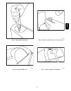
a. Verify vent pipe is cool to the touch.
b. Disconnect power to furnace andremove ventconnector
from furnace vent elbow.
c. Restorepower to furnace and setroom thermostat above
room temperature.
d. After normal start--up, allow furnace to operate for 2
minutes, then block vent elbow in furnace 80 percent of
vent area with a piece of flat sheet metal.
e. Furnaceshouldcycleoffwithin2 minutes.Ifgasdoesnot
shut off within 2 minutes, determine reason draft
safeguard switch did not function properly and correct
condition.
f. Remove blockage from furnace vent elbow.
g. Switch will auto--reset when it c ools.
h. Re--install vent connector.
NOTE: Should switch remain open longer than 3 minutes,
furnace control board will lockout the furnace for 3 hours. To
reset furnace control board, turn thermostat below room
temperature or from HEAT to OFF and turn 115v power OFF,
then back ON.
3. Check Pressure Switch
This control proves operation of the draft inducer blower.
a. Turn of f 115--v power to furnace.
b. Disconnect inducer motor lead wires from wire harness.
c. Turn on 115--v power to furnace.
d. Set thermostat to “call for heat” and wait 1 minute. When
pressure switch is functioning properly, hot surface
igniter should NOT glow and control diagnostic light
flashesastatuscode32.Ifhotsurfaceigniterglowswhen
inducer motor is disconnected, shut down furnace
immediately.
e. Determine reason pressure switch did not function
properly and correct condition.
f. Turn of f 115--v power to furnace.
g. Reconnect inducer motor wires, replace outer door, and
turn on 115--v power.
h. Blower will run for 90 sec before beginning the call
forheat again.
i. Furnace should ignite normally.
58PHA