


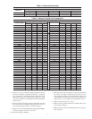

LOW CHARGE COOLING
024-042 units:
1. Measure suction line pressure by attaching a gauge to the
service port.
2. Measure the suction line temperature by attaching a tempera-
ture sensing device to it.
3. Insulate the temperature sensing device so that the outdoor
ambient doesn’t affect the reading.
4. Locate the measured suction line pressure in the top row of
Table 8 and the measured outdoor ambient temperature in the
left column of the table. Based on the two values, determine
the required suction line temperature.
5. If the measured suction line temperature is greater than the
tabulated temperature, add charge in the system.
048 and 060 units:
1. Measure discharge line pressure by attaching a gauge to the
service port.
2. Measure the liquid line temperature by attaching a temperature
sensing device to it.
3. Insulate the temperature sensing device so that the outdoor
ambient doesn’t affect the reading.
4. Refer to the required subcooling in Tables 4 and 5 to find the
required subcooling based on the model size and the outdoor
ambient temperature.
5. Interpolate if the outdoor temperature lies in between the table
values. Extrapolate if the temperature lies beyond the table
range.
6. Find the pressure value corresponding to the measured pres-
sure on the compressor discharge line.
7. Read across from the pressure reading to obtain the Liquid line
temperature for a required subcooling.
8. Add charge if the measured temperature is higher than the
liquid line temperature value in the table.
9. Add charge using the service connection on the suction line of
the compressor.
HEATING MODE CHARGE
Do not attempt to adjust charge by cooling methods while in heat
pump heating mode. Recover refrigerant and weigh in according to
unit data plate refrigerant data.
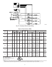
Step 4—Indoor Airflow and Airflow Adjustments
NOTE: For cooling operation, the recommended airflow is 350 to
450 cfm per each 12,000 Btuh of rated cooling capacity.
Table 7 shows dry coil air delivery for horizontal discharge units.
Tables 9-11 show pressure drops.
NOTE: Be sure that all supply- and return-air grilles are open,
free from obstructions, and adjusted properly.
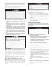
ELECTRICAL SHOCK HAZARD
Failure to follow this warning could result in personal injury
or death.
Disconnect electrical power to the unit and install lockout tag
before changing blower speed.
Airflow can be changed by changing the 24 volts lead connections
of the blower motor.
Unit 50ZHA blower motors are factory wired for rated airflow
operation.
FOR 208/230-V BLOWER MOTORS
The motor lead speed connections are as follows:
SIZE RATED AIRFLOW HIGH AIRFLOW
024 Tap 1 Tap 3
030 Tap 2 Tap 4
036 Tap 1 Tap 3
042 Tap 2 Tap 4
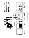
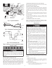
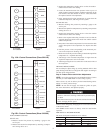
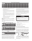
Thermostat
Unit Control
G
Y
W2
W3
R
RED
GREEN
YELLOW
O
ORANGE
C
BROWN
WHITE
VIOLET
and subbase
Power
A05207
Fig. 10A—Control Connections (Sizes 024-042)
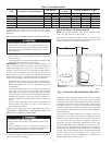
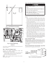
Thermostat
Unit Control
G
Y
Y1
O
R
RED
GREEN
YELLOW
W2
PINK
W3
ORANGE
WHITE
VIOLET
C
BROWN
Power
and subbase
A05208
Fig.10B—Control Connections (Sizes 048-060)
9