


Step 7—Install Electrical Connections
ELECTRICAL SHOCK HAZARD
Failure to follow this warning could result in personal injury
or death.
The unit cabinet must have an uninterrupted, unbroken
electrical ground to minimize the possibility of personal
injury if an electrical fault should occur. This ground may
consist of an electrical wire connected to the unit ground in
the control compartment, or conduit approved for electrical
ground when installed in accordance with NEC (National
Electrical Code), ANSI (American National Standards
Institute)/NFPA (latest edition) (in Canada, Canadian Elec-
trical Code CSA C22.1) and local electrical codes.
UNIT DAMAGE HAZARD
Failure to follow these precautions may result in damage to
the unit being installed:
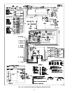
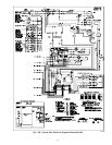
1. Make all electrical connections in accordance with NEC
ANSI/NFPA (latest edition) and local electrical codes
governing such wiring. In Canada, all electrical connec-
tions must be in accordance with CSA standard C22.1
Canadian Electrical Code Part 1 and applicable local
codes. Refer to unit wiring diagram.
2. Use only copper conductor for connections between
field-supplied electrical disconnect switch and unit. DO
NOT USE ALUMINUM WIRE.
3. Be sure that high-voltage power to unit is within operating
voltage range indicated on unit rating plate.
4. Insulate low-voltage wires for highest voltage contained
within conduit when low-voltage control wires are run in
same conduit as high-voltage wires.
5. Do not damage internal components when drilling through
any panel to mount electrical hardware, conduit, etc.
Consult local power company for correction of improper
voltage.
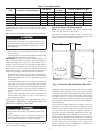
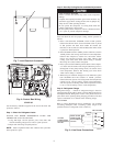
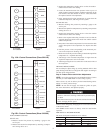
HIGH-VOLTAGE CONNECTIONS
The unit must have a separate electrical service with a field-
supplied, waterproof disconnect switch mounted at, or within sight
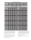
from the unit. Refer to the unit rating plate for maximum
fuse/circuit breaker size and minimum circuit amps (ampacity) for
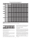
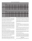
wire sizing. See Table 6 for electrical data.
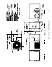
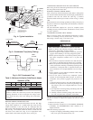
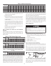
The field-supplied disconnect may be mounted on the unit over the
high-voltage inlet hole. (See Fig. 2.)
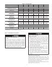
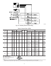
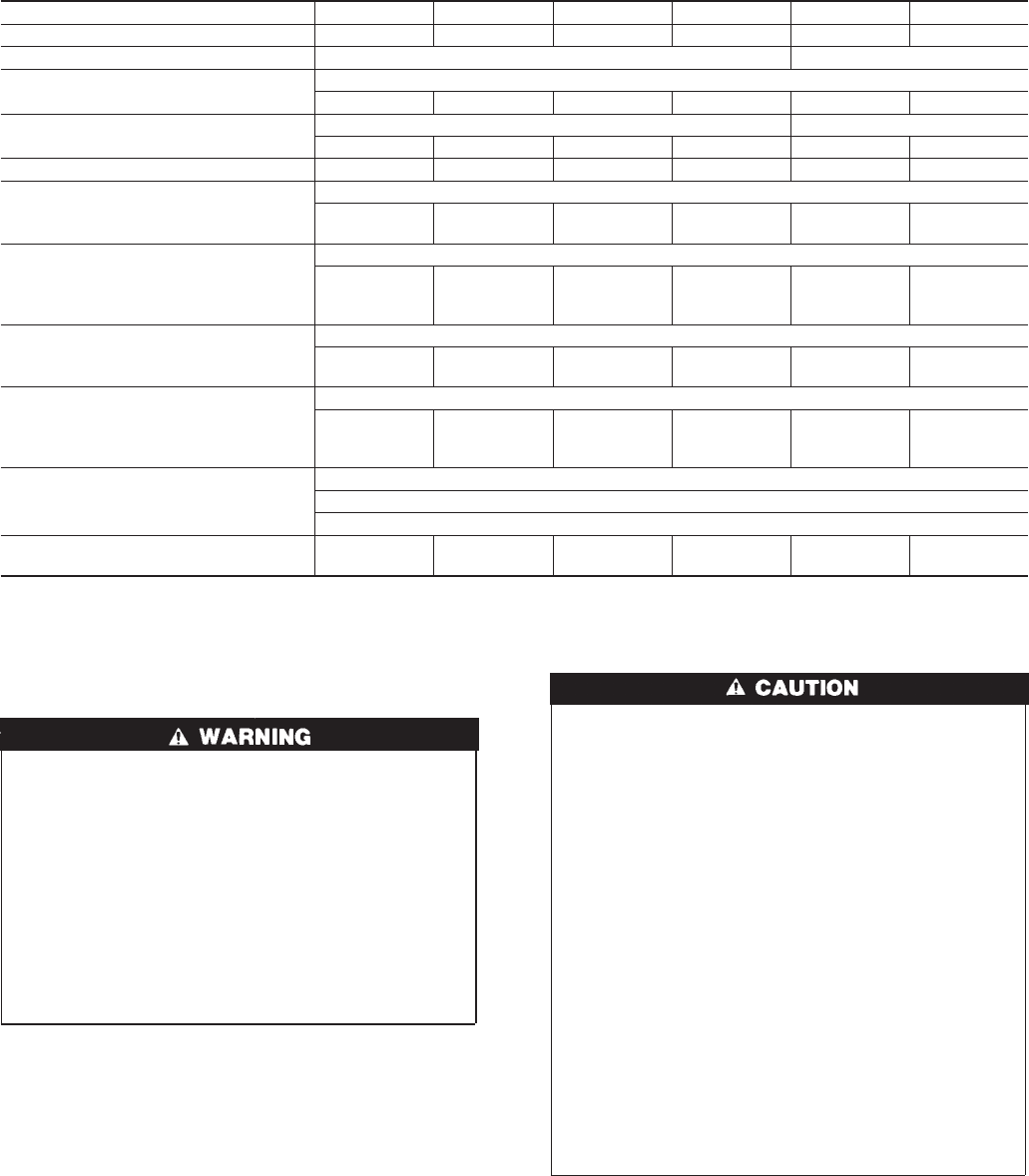
Table 2—Physical Data
UNIT 50ZHA 024 030 036 042 048 060
OPERATING WEIGHT (lbs) 293 324 377 389 384 433
COMPRESSOR TYPE Scroll Ultra Tech Scroll
REFRIGERANT Charge (lb)
R-22
7.5 10.3 10.3 11.9 11.4 13.3
REFRIGERANT METERING DEVICE
Orifice ID (in.)
Accurater TXV
.067 .067 .082 .086 — —
Orifice OD (in.) .049 .057 .059 .063 .070 .073
CONDENSER COIL
Rows...Fins/in.
Face Area (sq. ft.)
Copper Tubes, Aluminum Plate Fins
2...21
11.1
2...21
12.7
2...21
15.8
2...21
15.8
2...21
13.3
2...21
15.8
CONDENSER FAN
Nominal Cfm
Diameter (in.)
Motor HP (RPM)
Propeller
2600
20
1/8 (825)
2600
20
1/8 (825)
3200
20
1/4 (1100)
3200
20
1/4 (1100)
3200
20
1/4 (1100)
3300
20
1/2 (1100)
EVAPORATOR COIL
Face Area (sq. ft.)
Copper Tubes, Aluminum Plate Fins
3...17
4.3
3...17
4.9
4...17
4.9
4...17
6.1
4...17
4.9
4...17
6.1
Evaporator Blower
Nominal Airflow (CFM)
Size (in.)
Motor HP (RPM)
Direct Drive
800
10x8
1/2 (1050)
1000
10x8
1/2 (1050)
1200
11x9
3/4 (1050)
1400
11x9
3/4 (1050)
1600
11x10
1 (1050)
1875
11x10
1 (1050)
CONNECTING DUCT SIZES
Supply Air (in.)
Return Air (in.)
Round
14
14
Return-Air Filters (in.)*
Throwaway
24x24 24x24 24x24 24x30 30x30 30x30
*Required filter sizes shown are based on the ARI (Air Conditioning and Refrigeration Institute) rated airflow at a velocity of 300 ft/min for throwaway type or 450 ft/min
for high capacity type. Recommended filters are 1-in. thick.
5