


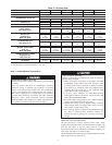
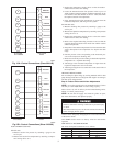
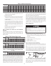
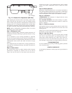

SIZE
RATED AIRFLOW HIGH AIRFLOW
Low
Stage
High
Stage
Low
Stage
High
Stage
048 Tap 1 Tap 3 Tap 2 Tap 4
060 Tap 1 Tap 3 Tap 2 Tap 4
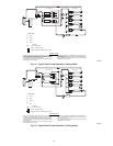
Step 5—Unit Controls
All compressors have the following internal-protection controls.
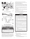
HIGH-PRESSURE RELIEF VALVE
This valve opens when the pressure differential between the low
and high side becomes excessive.
LOSS OF CHARGE SWITCH
Located on the outdoor liquid line is a low-pressure switch which
functions as a loss-of-charge switch. This switch contains a
Schrader core depressor. This switch opens at 7 psig and closes at
22 psig. No adjustment is necessary.
COMPRESSOR OVERLOAD
This overload interrupts power to the compressor when either the
current or internal temperature become excessive, and automati-
cally resets when the internal temperature drops to a safe level.
This overload may require up to 60 minutes (or longer) to reset;
therefore, if the internal overload is suspected of being open,
disconnect the electrical power to the unit and check the circuit
through the overload with an ohmmeter or continuity tester.
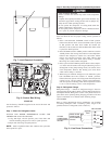
Step 6—Sequence of Operation
FAN OPERATION
The FAN switch on the thermostat controls indoor fan operation.
When the FAN switch is placed in the ON position, the IFR
(indoor-fan relay) is energized through the G terminal on the
thermostat. The normally-open contacts close, which then provide
power to the indoor (evaporator) fan motor (IFM). The IFM will
run continuously when the FAN switch is set to ON.
When the FAN switch is set to AUTO, the thermostat deenergizes
the IFR (provided there is not a call for cooling). The contacts open
and the IFM is deenergized. The IFM will be energized only when
there is a call for cooling, in heat pump heating mode or if the unit
is equipped with accessory electric heat, the indoor-fan motor will
also run while the accessory electric heat is energized.
NOTE: Some units are equipped with a time-delay relay. On
these units, the indoor fan remains on for 30 seconds after G or Y
is deenergized.
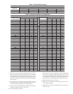
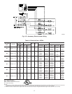
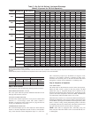
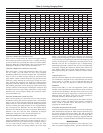
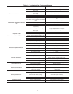
Table 7—Dry Coil Air Delivery* Horizontal Discharge
(Deduct 10 percent for 208 Volt Operation)
50ZHA SPEED TAP WATTS/C.F.M
EXTERNAL STATIC PRESSURE
0.1 0.2 .03 0.4 0.5 0.6 0.7 0.8 0.9 1.0
024
1
Watts -99100118130142----
C.F.M. -848793757698632----
2
Watts -----222233244257260
C.F.M -----970918861795729
030
2
Watts -155146157170-----
C.F.M - 1108 995 951 884 -----
3
Watts -----261275286291315
C.F.M. -----1117 1053 1014 980 877
036
1
Watts 180166179191204216----
C.F.M. 1344 1215 1172 1136 1095 1051 ----
2
Watts - - - 261 276 290 301 316 329 342
C.F.M. - - - 1343 1304 1272 1234 1190 1148 1100
042
3
Watts 269 283 305 321 336 349 360 - - -
C.F.M. 1440 1404 1369 1333 1301 1273 1239 - - -
4
Watts - - 418 432 450 465 480 490 503 518
C.F.M. - - 1572 1543 1504 1475 1441 1418 1380 1332
048
1
Watts — 204 209 216 229 236 249 — — —
C.F.M. — 1129 1087 1027 994 932 881 — — —
2
Watts — — 233 245 254 266 276 289 — —
C.F.M. — — 1164 1122 1066 1025 954 906 — —
3
Watts 386 398 409 418 425 435 438 441 451 —
C.F.M. 1680 1652 1625 1583 1555 1515 1477 1444 1403 —
4
Watts — 440 448 457 462 469 477 480 485 486
C.F.M. — 1745 1717 1684 1651 1612 1573 1537 1508 1470
060
1
Watts 224 235 251 266 277 291 298 - - -
C.F.M. 1334 1288 1259 1224 1181 1157 1117 - - -
2
Watts - - 286 301 311 325 333 344 370 -
C.F.M. - - 1333 1296 1261 1232 1199 1170 1062 -
3
Watts 608 626 643 660 668 685 697 - - -
C.F.M. 1931 1900 1878 1844 1817 1789 1755 - - -
4
Watts 737 755 770 787 799 817 826 812 782 -
C.F.M. 2093 2061 2028 2001 1971 1934 1899 1850 1757 -
Air delivery values are based on operating voltage of 230-v., dry coil, without filter or electric heater. Deduct wet coil, filter, and electric heater pressure drops to obtain
external static pressure availabe for ducting.
Do not operate the unit at a cooling airflow that is less than 350 cfm for each 12,000 Btuh of rated cooling capacity. Evaporator coil frosting may occur at airflows below
this point.
Dashes indicate portions of the table that are beyond the blower motor capacity or are not recommended.
13