


are field-installed and must be removed from the indoor blower
compartment prior to start-up, even if they are not used for
installation.
When designing and installing ductwork, consider the following:
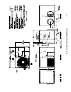
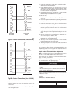
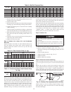
UNIT DAMAGE HAZARD
Failure to follw this caution may result in damage to unit
components. When connecting ductwork to units, do not drill
deeper than 3/4 inch in shaded area shown in Fig. 3 or coil
may be damaged.
• All units should have field-supplied filters installed in the
return-air side of the unit. Recommended sizes for filters are
shown in Table 2.
• Avoid abrupt duct size increases and reductions. Abrupt change
in duct size adversely affects air performance.
IMPORTANT: Use flexible connectors between ductwork and
unit to prevent transmission of vibration. Use suitable gaskets to
ensure weathertight and airtight seal. When electric heat is
installed, use fire proof canvas (or similar heat resistant material)
connector between ductwork and unit discharge connection. If
flexible duct is used, insert a sheet metal sleeve inside duct. Heat
resistant duct connector (or sheet metal sleeve) must extend 24–in.
from the unit discharge connection flange into the ductwork.
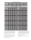
• Size ductwork for cooling air quantity (cfm). The minimum air
quantity for proper electric heater operation is listed in Table 3.
Heater limit switches may trip at air quantities below those
recommended.
• Insulate and weatherproof all external ductwork. Insulate and
cover with a vapor barrier all ductwork passing through
conditioned spaces. Follow latest Sheet Metal and Air Condi-
tioning Contractors National Association (SMACNA) and Air
Conditioning Contractors Association (ACCA) minimum in-
stallation standards for residential heating and air conditioning
systems.
• Secure all ducts to building structure. Flash, weatherproof, and
vibration-isolate duct openings in wall or roof according to
good construction practices.
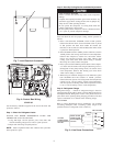
Figure 4 shows a typical duct system with 50ZHA unit installed.
CONVERTING HORIZONTAL DISCHARGE UNITS TO
DOWNFLOW (VERTICAL) DISCHARGE
ELECTRICAL SHOCK HAZARD
Failure to follow this warning could result in personal injury
or death.
Before performing service or maintenance operations on
system, turn off main power to unit and install lockout tag.
Turn off accessory heater power switch if applicable.
Units are dedicated side supply products. They are not convertible
to vertical air supply. A field-supplied plenum must be used to
convert to vertical air discharge.
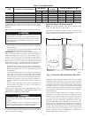
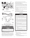
Step 6—Provide for Condensate Disposal
NOTE: Be sure that condensate-water disposal methods comply
with local codes, restrictions, and practices.
Unit removes condensate through a 1 3/64-in. ID hole (using
3/4-in. OD piping or tubing) which is located at the end of the unit.
See Fig. 2 for location of condensate connection.
Condensate water can be drained directly onto the roof in rooftop
installations (where permitted) or onto a gravel apron in ground-
level installations. Install a field-supplied condensate trap at end of
condensate connection to ensure proper drainage. Make sure that
the outlet of the trap is at least 1 in. lower than the drain-pan
condensate connection to prevent the pan from overflowing. Prime
the trap with water. When using a gravel apron, make sure it slopes
away from the unit.
If the installation requires draining the condensate water away
from the unit, install a 2-in. trap using a 3/4-in. OD tubing or pipe.
(See Fig. 5 and 6.) Make sure that the outlet of the trap is at least
1 in. lower than the unit drain-pan condensate connection to
prevent the pan from overflowing. Prime the trap with water.
Connect a drain tube using a minimum of 3/4-in. PVC, 3/4-in.
CPVC, or 3/4-in. copper pipe (all field supplied). Do not undersize
the tube. Pitch the drain tube downward at a slope of at least 1 in.
for every 10 ft of horizontal run. Be sure to check the drain tube
for leaks. Prime trap at the beginning of the cooling season
start-up. Allowable glues for condensate trap connection are:
Standard ABS, CPVC, or PVC cement.
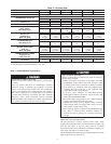
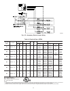
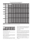
Table 1—Unit Specifications
UNIT ELECTRICAL CHARACTERISTICS
UNIT WEIGHT
UNIT HEIGHT
IN. (MM)
CENTER OF GRAVITY IN. (MM)
lb kg ″A″ XYZ
50ZHA024 208/230-1-60 293 133 30.13 (765) 14.0 (356) 19.0 (483) 12.0 (305)
50ZHA030 208/230-1-60 324 147 34.13 (867) 14.0 (356) 19.0 (483) 12.0 (305)
50ZHA036 208/230-1-60 377 171 42.13 (1070) 14.0 (356) 19.0 (438) 19.8 (503)
50ZHA042 208/230-1-60 389 177 42.13 (1070) 14.0 (356) 19.0 (483) 21.9 (556)
50ZHA048 208/230-1-60 384 175 42.13 (1070) 14.0 (356) 19.0 (483) 19.8 (503)
50ZHA060 208/230-1-60 433 197 42.13 (1070) 14.0 (356) 19.0 (483) 21.9 (556)
Fig. 3—Area Not to Be Drilled More Than 3/4-in.
19.17
3.92
A05195
4