


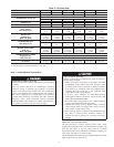
COOLING OPERATION (SIZES 024-042)
With a call for cooling (Y/Y2), the indoor fan energizes immedi-
ately whereas the contactor energizes aftera5minute time delay
(in case of initial start-up) starting the compressor and the outdoor
fan motor. When the cooling demand is met, Y/Y2 de-energizes,
shutting the compressor, indoor fan and the outdoor fan.
COOLING OPERATION (SIZES 048 AND 060)
These units utilize a 2 stage indoor thermostat. With a first stage
call for cooling (Y1), the indoor fan (low stage) energizes
immediately whereas the contactor energizes aftera5minute time
delay (in case of an initial start-up) starting the compressor (low
stage) and the outdoor fan motor. If the low stage operation cannot
satisfy the cooling demand, the second stage cooling (Y2) ener-
gizes switching the compressor into high stage cooling through
energizing an internal solenoid valve inside the scroll compressor
and switching the indoor fan into high stage. When second stage
cooling is satisfied, Y2 de-energizes switching the compressor and
the indoor fan into low stage cooling. When the low stage cooling
demand is met, Y1 de-energizes shutting the compressor, indoor
fan and the outdoor fan.
HEATING OPERATION (SIZES 024-042)
With a call for heating (Y1), the indoor fan (low stage) energizes
immediately whereas the contactor energizes aftera5minute time
delay (in case of initial start-up) starting the compressor and the
outdoor fan motor. If Y/Y2 cannot satisfy the heating demand, the
auxiliary or backup heat (W2) energizes. In case of staged heating,
W3 is energized if the demand is not met. The highest airflow
selected is run while the electric heat is in operation. When heating
demand is met, W3, W2 and Y/Y2 sequentially de-energize
shutting the compressor, indoor fan and the outdoor fan.
HEATING OPERATION (SIZES 048 AND 060)
With a first stage call for heating (Y1), the indoor fan (low stage)
energizes immediately whereas the contactor energizes after a 5
minute time delay (in case of initial start-up) starting the compres-
sor (low stage) and the outdoor fan motor. If the low stage
oepration cannot satisfy the heating demand, the second stage
heating (Y2) energizes switching the compressor into high stage
heating through energizing an internal solenoid valve inside the
scroll compressor and switching the indoor fan into high stage. The
auxiliary or backup heat is controlled by a third stage (W2). If the
demand is not met, W3 is energized in case of staged heating.
When heating demand is satisfied, W3, W2 and Y2 sequentially
de-energize switching the compressor and the indoor fan into low
stage heating. When the low stage heating demand is met, Y1
de-energizes shutting the compressor, indoor fan and the outdoor
fan.
CONTINUOUS FAN
With the continuous Indoor fan option selected on the thermostat,
G is continuously energized. In case of 024-042 units, the selected
airflow setting is provided. In case of 048 and 060 units, the
system runs low stage (Y1) airflow for continuous fan operation.
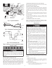
DEFROST
Defrost board (DB) is a time and temperature control, which
includes a field-selectable time period between checks for defrost
(30, 60, 90 and 120 minutes). The time period is factory-set at 60
minutes and should only be adjusted by a trained service person.
Electronic timer and defrost cycle start only when contactor is
energized and defrost thermostat (DFT) is closed.
Defrost mode is identical to Cooling mode. The outdoor fan motor
stops because of “OF1” and “OF2” contacts opening on the defrost
board, a bank of optional electric heat turns on to warm air
supplying the conditioned space.
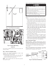
ELECTRIC RESISTANCE HEATING
If accessory electric heaters are installed, on a call for “Emergency
Heat” the thermostat energizes W which energizes the heater relay
and in turn energizes the electric heaters. The IFR is energized
which starts the indoor-fan motor. If the heaters are staged, W2 is
energized when the second stage of heating is required. When the
need for heating is satisfied, the heater and IFM are de-energized.
MAINTENANCE
To ensure continuing high performance, and to reduce the possi-
bility of premature equipment failure, periodic maintenance must
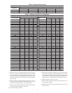
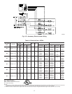
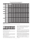
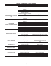
Table 8—Cooling Charging Chart
SUCTION LINE TEMPERATURE (°F)
Suction Line Pressure (PSIG)
OD Temp. (°F) 52 54 56 59 61 64 67 70 73 76 79 82 85 89 92
45 51 55606469——————————
55 — —5357626670————————
65 — ———535762667175—————
75 — ——————5661667176———
85 — ———————5358636772——
95 — ————————5054586266—
105 — —————————5053576064
115 — —————————4952555861
125 — ——————————50535659
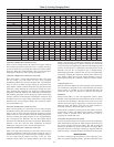
SUCTION LINE TEMPERATURE (°C)
Suction Line Pressure (kPa)
OD Temp. (°C) 361 370 387 405 423 442 462 482 502 523 544 566 589 612 636
7 11 13151821——————————
13 — —1214161921————————
18 — ———121417192124—————
24 — ——————1316192224———
29 — ———————1214172022——
35 — ————————1012141719—
41 — —————————1012141618
46 — ————————— 911131416
52 — ——————————10111315
14