


START-UP
Use the Start-Up Checklist supplied at the end of this book and
proceed as follows:
Step 1—Check for Refrigerant Leaks
LOCATE AND REPAIR REFRIGERANT LEAKS AND
CHARGE THE UNIT AS FOLLOWS:
1. Using both high- and low-pressure ports, locate leaks and
reclaim remaining refrigerant to relieve system pressure.
2. Repair leak following accepted practices.
NOTE: Install a liquid-line filter drier whenever the system has
been opened for repair.
Step 2—Start-Up Cooling Section and Make Adjustments
UNIT DAMAGE HAZARD
Failure to follow this caution may result in unit component
damage.
Complete the required procedures given in the Pre-Start- Up
section this page before starting the unit. Do not jumper any
safety devices when operating the unit.
Do not operate the compressor in cooling mode when the
outdoor temperature is below 40 F.
Do not rapid-cycle the compressor. Allow 5 minutes between
‘‘on’’ cycles to prevent compressor damage.
CHECKING COOLING CONTROL OPERATION
Start and check the unit for proper cooling control operation as
follows:
1. Place room thermostat SYSTEM switch in OFF position.
Observe that blower motor starts when FAN switch is placed
in ON position and shuts down within 60 seconds (for
024-042) or 90 seconds (for 048 and 060) when FAN switch
is placed in AUTO position.
2. Place SYSTEM switch in COOL position and FAN switch in
AUTO position. Set cooling control below room temperature.
Observe that compressor, outdoor fan, and indoor blower
motors start and that reversing valve shifts. Observe that
cooling cycle shuts down when control setting is satisfied.
Reversing valve (RV) remains energized.
3. Place system switch in HEAT position. Observe that compres-
sor, indoor fan and outdoor fan energize (Reversing Valve is
deenergized in heat pump heating mode). Set control above
room temperature. Observe that heating cycle shuts down
when control setting is satisfied.
4. When using an automatic changeover room thermostat, place
both SYSTEM and FAN switches in AUTO. positions.
Observe that unit operates in Cooling mode when temperature
control is set to ‘‘call for cooling’’ (below room temperature),
and unit operates in Heating mode when temperature control
is set to “call for heating” (above room temperature).
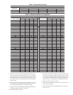
Step 3—Refrigerant Charge
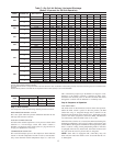
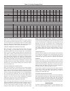
Refrigerant Charge — Amount of refrigerant charge is listed on
unit nameplate and in Table 2. Refer to Carrier Refrigerant Service
Techniques Manual, Refrigerants section. Unit panels must be in
place when unit is operating during charging procedure. Unit must
operate a minimum of 15 minutes before checking charge.
NO CHARGE
Refer to Carrier Refrigerant Service Techniques. Use standard
evacuating techniques. After evacuating system, weigh in the
specified amount of refrigerant (refer to Table 2).
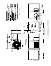
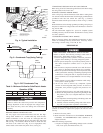
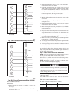
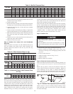
Fig. 7—Unit Electrical Connection
A05198
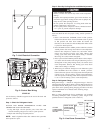
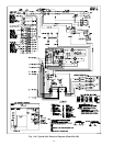
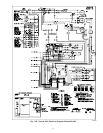
Fig. 8—Control Box Wiring
C00011
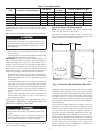
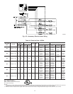
3-PHASE
CONNECTIONS
TO DISCONNECT
PER NEC
SINGLE-PHASE
CONNECTIONS
TO DISCONNECT
PER NEC
GROUND
LEAD
UNIT GROUND
BLK
YEL
BLU
L
L
L
C00012
Fig. 9—Line Power Connections
8