


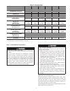
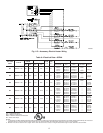
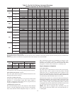

Table 3—Minimum Airflow for Safe Electric Heater
Operation (CFM)
SIZE 024 030 036 042 048 060
Cfm 600 750 900 1050 1200 1500
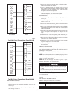
UNIT DAMAGE HAZARD
Failure to follow this caution may result in unit component
damage. Operation of unit on improper line voltage consti-
tutes abuse and may cause unit damage that could affect
warranty.
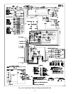
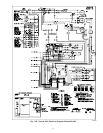
ROUTING POWER LEADS INTO UNIT
Use only copper wire between disconnect and unit. The high-
voltage leads should be in a conduit until they enter the unit;
conduit termination at the unit must be watertight. Run the
high-voltage leads through the hole on the control box side of the
unit (see Fig. 7 for location). When the leads are inside the unit,
run leads to the control box (Fig. 8). For single-phase units,
connect leads to the black and yellow wires (see Fig. 9).
CONNECTING GROUND LEAD TO UNIT GROUND
Refer to Fig. 8 and 9. Connect the ground lead to the chassis using
the unit ground in the control box.
ROUTING CONTROL POWER WIRES
Form a drip-loop with the thermostat leads before routing them
into the unit. Route the thermostat leads through grommeted hole
provided in unit into unit control box (See Fig. 7). Connect
thermostat leads and unit power leads as shown in Fig. 9, 10A &
10B.
Route thermostat wires through grommet providing a drip-loop at
the panel. Connect low-voltage leads to the thermostat as shown in
Fig. 10A & 10B.
The unit transformer supplies 24-v power for complete system
including accessory electrical heater. Transformer is factory wired
for 230-v operation.
ACCESSORY ELECTRIC HEAT WIRING
Refer to accessory electric heat installation instructions for infor-
mation on installing accessory electric heat. Accessory electric
heat wiring is shown in Fig. 11A, 11B, & 11C.
PRE-START-UP
FIRE, EXPLOSION, ELECTRICAL SHOCK HAZARD
Failure to observe the following warnings could result in
serious injury, death and/or property damage:
1. Follow recognized safety practices and wear protective
goggles when checking or servicing refrigerant system.
2. Do not operate compressor or provide any electric power to
unit unless compressor terminal cover is in place and
secured.
3. Do not remove compressor terminal cover until all electri-
cal sources are disconnected and lockout tag is installed.
4. Relieve all pressure from both high- and low-pressure sides
of the system before touching or disturbing anything inside
terminal box if refrigerant leak is suspected around com-
pressor terminals. Use accepted methods to recover refrig-
erant.
5. Never attempt to repair soldered connection while refrig-
erant system is under pressure.
6. Do not use torch to remove any component. System
contains oil and refrigerant under pressure. To remove a
component, wear protective goggles and proceed as fol-
lows:
a. Shut off electrical power to unit and install lockout tag.
b. Relieve all refrigerant from system using both high- and
low-pressure ports. Use accepted methods to recover
refrigerant.
c. Cut component connecting tubing with tubing cutter and
remove component from unit.
d. Carefully unsweat remaining tubing stubs when neces-
sary. Oil can ignite when exposed to torch flame.
Use the Start-Up Checklist supplied at the end of this book and
proceed as follows to inspect and prepare the unit for initial
start-up:
1. Remove all access panels.
2. Read and follow instructions on all DANGER, WARNING,
CAUTION, and INFORMATION labels attached to, or
shipped with unit.
Make the following inspections:
a. Inspect for shipping and handling damages such as broken
lines, loose parts, disconnected wires, etc.
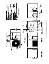
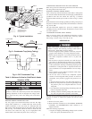
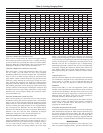
Fig. 4—Typical installation
C00008
C00008
TOP COVER
INDOOR
THERMOSTAT
DISCONNECT
PER NEC*
(UNIT AND
ELECTRIC
HEATER)
FROM
POWER
SOURCE
RETURN
AIR
POWER AND
LOW-VOLTAGE
ENTRY
COMPOSITE
RUST-PROOF
BASEPAN
CONDENSATE
DRAIN
CONNECTION
*Separate disconnect per NEC
(National Electrical Code) required
for electric heater when single-
point conection is not used.
Power Wiring
Control Wiring
Condenser Airflow
Evaporator Airflow
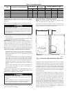
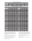
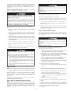
Fig. 5—Condensate Trap (Using Tubing)
C99013
1” (25mm) MIN.
2” (50mm) MIN.
TRAP
OUTLET
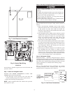
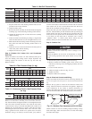
Fig. 6—PVC Condensate Trap
C00009
TRAP
OUTLET
2" min.
1" min.
6