


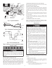
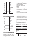
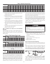
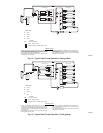
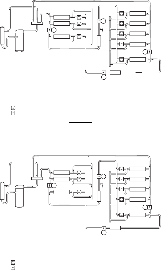
Fig. 14—Typical Heat Pump Operation, Heating Mode
C95045
STRAINER
ACCUMULATOR
COMPRESSOR
STRAINER
LCS
OUTDOOR COIL
INDOOR COIL
A
B
D
C
Check Valves
A
Open
B
Closed
C
Open
D
Closed
LEGEND
LCS Loss of Charge Switch
Acutrol Metering Device
Check Valve (Arrow indicates direction of flow)
HEATING CYCLE
1. Hot gas from compressor flows through the 4-way valve and is
directedtothecoolingliquid linecheckvalve. Itisthencondensed
and directed through subcooling circuits and out to the strainer
and the check valve in the heating liquid line.
2. The refrigerant then feeds the outdoor coil through the Acutrol
metering device on each circuit.
3. Each circuit evaporates the refrigerant and the circuits are com-
binedinthe outdoorheader withsome ofthe circuitsflowing through
the check valve.
4. The refrigerant then flows through the 4-way valve, accumulator,
and back to the compressor.
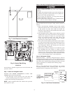
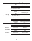
Fig. 15—Typical Heat Pump Operation, Cooling Mode
C95044
STRAINER
ACCUMULATOR
COMPRESSOR
STRAINER
LCS
OUTDOOR COIL
INDOOR COIL
A
B
D
C
Check Valves
A
Closed
B
Open
C
Closed
D
Open
LEGEND
LCS Loss of Charge Switch
Acutrol Metering Device
Check Valve (Arrow indicates direction of flow)
COOLING CYCLE
1. Hot gas from compressor flows through the 4-way valve and is
directed to the heating liquid line check valve. It is then con-
densedand subcooledthrough convergingcircuits.Refrigerantleaves
the outdoor coil by way of the strainer and the check valve in the
cooling liquid line.
2. The refrigerant then feeds the indoor coil through the Acutrol
metering device on each circuit.
3. Each circuit evaporates the refrigerant and the circuits are com-
bined in the indoor coil header with some of the circuits flowing
through the check valve.
4. The refrigerant then flows through the 4-way valve, accumulator,
and back to the compressor.
18