


Follow all safety codes. Wear safety glasses and work gloves. Use
quenching cloth for unbrazing operations. Have fire extinguisher
available for all brazing operations.
FIRE, EXPLOSION, ELECTRICAL SHOCK HAZARD
Failure to follow this warning could result in personal injury,
death and/or property damage.
Before performing service or maintenance operations on
system, turn off main power to unit and install lockout tag.
Turn off accessory heater power switch if applicable.
Recognize safety information. This is the safety-alert symbol .
When you see this symbol in instructions or manuals, be alert to
the potential for personal injury.
Understand the signal words DANGER, WARNING, CAUTION,
and NOTE. These words are used with the safety-alert symbol.
DANGER identifies the most serious hazards which will result in
severe personal injury or death. WARNING signifies a hazard
which could result in personal injury or death. CAUTION is used
to identify unsafe practices which may result in minor personal
injury or product and property damage. NOTE is used to highlight
suggestions which will result in enhanced installation, reliability,
or operation.
These instructions cover minimum requirements and conform to
existing national standards and safety codes. In some instances,
these instructions exceed certain local codes and ordinances,
especially those that may not have kept up with changing residen-
tial construction practices. We require these instructions as a
minimum for a safe installation.
INTRODUCTION
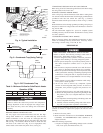
50ZHA heat pump units are fully self-contained and designed for
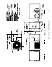
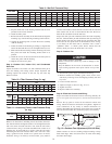
outdoor installation (See Fig. 1). As shown in Fig. 2, units are
shipped in a horizontal-discharge configuration for installation on
a ground-level slab. All units can be field-converted to downflow
discharge configurations for rooftop applications with a field-
supplied plenum.
RECEIVING AND INSTALLATION
Step 1—Check Equipment
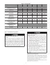
IDENTIFY UNIT
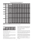
The unit model number and serial number are stamped on the unit
identification plate. Check this information against shipping pa-
pers. Verify that unit voltage and amperage listed on unit rating
plate agree with power supplied for equipment.
INSPECT SHIPMENT
Inspect for shipping damage while unit is still on shipping pallet.
If unit appears to be damaged or is torn loose from its securing
points, have it examined by transportation inspectors before
removal. Forward claim papers directly to transportation company.
Manufacturer is not responsible for any damage incurred in transit.
Check all items against shipping list. Immediately notify the
nearest Carrier Distributor if any item is missing.
To prevent loss or damage, leave all parts in original packages
until installation.
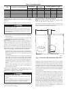
Step 2—Provide Unit Support
SLAB MOUNT
Place the unit on a rigid, level surface, suitable to support the unit
weight. A concrete pad or a suitable fiberglass mounting pad is
recommended. The flat surface should extend approximately 2-in.
beyond the unit casing on the 2 sides. The duct connection side and
condensate drain connection sides should be flush with the edge of
the flat surface.
A 6-in. wide gravel apron should be used around the flat surface to
prevent airflow blockage by grass or shrubs. Do not secure the unit
to the flat surface except where required by local codes.
The unit should be level to within 1/4 inch. This is necessary for
the unit drain to function properly.
GROUND MOUNT
The unit may also be installed directly on the ground if local codes
permit. Place unit on level ground prepared with gravel for
condensate discharge.
HURRICANE HOLD DOWN
Contact you local distributor for specific hurricane hold down
details and PE (Professional Engineer) certification when required.
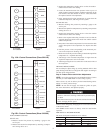
Step 3—Provide Clearances
The required minimum service clearances and clearances to
combustibles are shown in Fig. 2. Adequate ventilation and
outdoor coil air must be provided.
The outdoor fan pulls air through the outdoor coil and discharges
it through the fan on the top cover. Be sure that the fan discharge
does not recirculate to the outdoor coil. Do not locate the unit in
either a corner or under an overhead obstruction. The minimum
clearance under a partial overhang (such as a normal house
overhang) is 48 in. above the unit top. The maximum horizontal
extension of a partial overhang must not exceed 48 inches.
Do not place the unit where water, ice, or snow from an overhang
or roof will damage or flood the unit. The unit may be installed on
wood flooring or on Class A, B, or C roof covering materials.
OPERATIONAL HAZARD
Failure to follow this caution may result in unit component
damage.
Do not restrict outdoor coil airflow. An air restriction at either
the outdoor-air inlet or the fan discharge can be harmful to
compressor life.
Step 4—Place Unit
Unit can be moved with the rigging holds provided in the unit base.
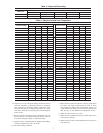
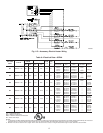
Refer to Table 2 for operating weights. Use extreme caution to
prevent damage when moving the unit. Unit must remain in an
upright position during all moving operations. The unit must be
level with in 1/4” for proper condensate drainage; the ground-level
pad must be level before setting the unit in place. When a
field-fabricated support is used, be sure that the support is level
and that it properly supports the unit.
Step 5—Select and Install Ductwork
The design and installation of the duct system must be in
accordance with:
• the standards of the NFPA (National Fire Protection Associa-
tion) for installation of nonresidence-type air conditioning and
ventilating systems
• NFPA90A or residence-type, NFPA90B; and/or local codes
and residence-type, NFPA 90B
• and/or local codes and ordinances
Select and size ductwork, supply-air registers and return-air grilles
according to ASHRAE (American Society of Heating, Refrigera-
tion, and Air Conditioning Engineers) recommendations.
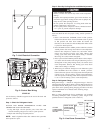
Use the duct flanges provided on the supply- and return-air
openings on the side of the unit. See Fig. 2 for connection sizes and
locations. The 14-in. round duct collars are shipped inside the unit
attached to the base pan in the indoor blower compartment. They
2