


a. Slip the wheel back in the housing with the hub set screw
parented in the correct direction.
b. Install the filler panel.
c. Reinsert the motor assembly in the wheel hub and align the
mounting legs with the housing mounting hold locations.
d. Tighten the mounting bolts to fasten the motor assembly
with the housing.
e. Center the wheel in the housing by sliding it, align the flat
end of the shaft with the set screw and tighten the set screw.
f. Slide back the blower housing into the mounting rails in the
duct panel and install the mounting bracket back in its
position.
g. Install the screws on the external side of the duct panel to
fasten duct panel with the housing.
h. Replace the side access panel.
Step 4—Outdoor Coil, Indoor Coil, and Condensate
Drain Pan
Inspect the outdoor coil, indoor coil, and condensate drain pan at
least once heating and cooling season. Proper inspection and
cleaning requires the removal of the unit top. See Unit Top
Removal section.
Remove all obstructions (including weeds and shrubs) that inter-
fere with the airflow through the outdoor coil. Straighten bent fins
with a fin comb. If coated with dirt or lint, clean the coils with a
vacuum cleaner, using a soft brush attachment. Be careful not to
bend the fins. If coated with oil or grease, clean the coils with a
mild detergent-and-water-solution. Rinse coils with clear water,
using a garden hose. Be careful not to splash water on motors,
insulation, wiring or air filter(s). For best results, spray outdoor-
coil fins from inside to outside the unit. On units with an outer and
inner outdoor coil, be sure to clean between the coils. Be sure to
flush all dirt and debris from the unit base.
Inspect the drain pan and condensate drain line when inspecting
the coils. Clean the drain pan and condensate drain by removing all
foreign matter from the pan. Flush the pan and drain tube with
clear water. Do not splash water on the insulation, motor, wiring,
or air filter(s). If the drain tube is restricted, clear it with a
‘‘plumbers snake’’ or similar probe device. Ensure that the
auxiliary drain port above the drain tube is also clear.
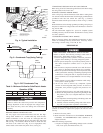
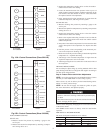
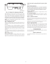
Step 5—Outdoor Fan
UNIT OPERATIONAL HAZARD
Failure to follow this caution may result in damage to unit
components.
Keep the Outdoor fan free from all obstructions to ensure
proper cooling operation. Never place articles on top of the
unit.
1. Shut off unit power supply and install lockout tag.
2. Remove outdoor-fan assembly (grille, motor, motor cover,
and fan) by removing screws and flipping assembly onto unit
top cover.
3. Loosen fan hub setscrews.
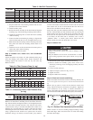
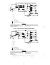
4. Adjust fan height as shown in Fig. 12 or 13.
5. Tighten setscrews.
6. Replace outdoor-fan assembly.
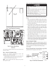
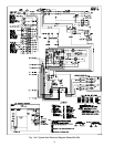
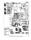
Step 6—Electrical Controls and Wiring
Inspect and check the electrical controls and wiring annually. Be
sure to turn off the electrical power to the unit and install lockout
tag.
Remove the top panel to locate all the electrical controls and
wiring. Check all electrical connections for tightness. Tighten all
screw connections. If any smoky or burned connections are
noticed, disassemble the connection, clean all the parts, restrip the
wire end and reassemble the connection properly and securely.
Check to ensure no wires are touching refrigerant tubing or sharp
sheet metal edges. Move and secure wires to isolate from tubing
and sheet metal edges.
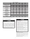
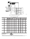
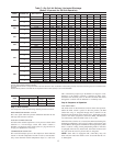
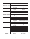
Table 9—Wet Coil Pressure Drop
UNIT SIZE
STANDARD CFM (S.C.F.M.)
600 700 800 900 1000 1100 1200 1300 1400 1500 1600 1700 1800 1900 2000
024 .027.034040.047.053----------
030 - .036 .042 .050 .055 .063 .072 .081 - - - - - - -
036 - - - .050 .055 .063 .072 .081 .090 .097 - - - - -
042 - - - - .042 .049 .052 .059 .065 .071 .078 .085 .091 - -
048 - - - - - - .072 .081 .090 .097 .108 .120 .129 .139 -
060 - - - - - - - - - .071 .078 .085 .091 .098 .114
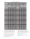
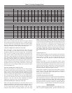
Table 10—Filter Pressure Drop (in. wg)
UNIT
SIZE
FILTER
SIZE
(IN.)
CFM
500 600 700 800 900 1000 1100 1200 1300 1400
024-036 24 x 24 0.06 0.07 0.08 0.08 0.09 0.09 0.09 0.10 0.11 0.12
042-060 30x30------ - -0.080.09
UNIT
SIZE
FILTER
SIZE
(IN.)
CFM
1500 1600 1700 1800 1900 2000 2100 2200 2300
024-036 24x240.140.15-------
042-060 30 x 30 0.10 0.11 0.12 0.13 0.14 0.15 0.16 0.17 0.18
Table 11—Accessory Electric Heat Pressure Drop
(in. wg)
HEATER KW
5-20
CFM
600 800 1000 1200 1400 1600 1800 2000 2200
0.06 0.08 0.10 0.13 0.15 0.18 0.20 0.23 0.25
Fig. 12—Outdoor-Fan Adjustment (024–048 Size)
C00021
3.125 in.
16