


4. Connect the RED lead to the BLK wire from which the ORG
lead was disconnected. Insulate with wirenut from Step 1.
5. Using the wirenut removed from the RED lead, insulate the
loose terminal on the ORG lead.
6. Wrap the wirenuts with electrical tape so that the metal
terminals cannot be seen.
Indoor blower-motor speeds may need to be changed for 208-v
operation. Refer to Indoor Airflow and Airflow Adjustments
section. (See Table of Contents for page number.)
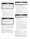
PRE-START-UP
Failure to observe the following warnings could result in
serious injury or death:
1. Follow recognized safety practices and wear protective
goggles when checking or servicing refrigerant system.
2. Do not operate compressor or provide any electric power to
unit unless compressor terminal cover is in place and
secured.
3. Do not remove compressor terminal cover until all electri-
cal sources are disconnected and lockout tag is installed.
4. Relieve all pressure from both high- and low-pressure sides
of the system before touching or disturbing anything inside
terminal box if refrigerant leak is suspected around com-
pressor terminals. Use accepted methods to recover refrig-
erant.
5. Never attempt to repair soldered connection while refrig-
erant system is under pressure.
6. Do not use torch to remove any component. System
contains oil and refrigerant under pressure. To remove a
component, wear protective goggles and proceed as fol-
lows:
a. Shut off electrical power to unit and install lockout tag.
b. Relieve all refrigerant from system using both high- and
low-pressure ports. Use accepted methods to recover
refrigerant.
c. Cut component connecting tubing with tubing cutter and
remove component from unit.
d. Carefully unsweat remaining tubing stubs when neces-
sary. Oil can ignite when exposed to torch flame.
Use the Start-Up Checklist supplied at the end of this book and
proceed as follows to inspect and prepare the unit for initial
start-up:
1. Remove all access panels.
2. Read and follow instructions on all DANGER, WARNING,
CAUTION, and INFORMATION labels attached to, or
shipped with, unit.
Make the following inspections:
a. Inspect for shipping and handling damages such as broken
lines, loose parts, disconnected wires, etc.
b. Inspect for oil at all refrigerant tubing connections and on
unit base. Detecting oil generally indicates a refrigerant
leak. Leak-test all refrigerant tubing connections using
electronic leak detector, or liquid-soap solution. If a refrig-
erant leak is detected, see following Check for Refrigerant
Leaks section.
c. Inspect all field- and factory-wiring connections. Be sure
that connections are completed and tight. Ensure wires do
not contact refrigerant tubing or sheet metal edges.
d. Inspect coil fins. If damaged during shipping and handling,
carefully straighten fins with a fin comb.
3. Verify the following conditions:
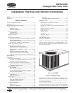
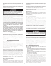
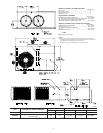
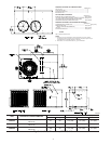
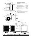
a. Make sure that outdoor-fan blade is correctly positioned in
fan orifice. Top edge of blade should be 3.125 in. down
from outdoor coil outlet grille (size 024–048, See Fig. 21)
or hub should be 0.708-in. away from motor end bell (size
060, See Fig. 22). See Outdoor Fan Adjustment section.
b. Make sure that air filter is in place.
c. Make sure that condensate drain trap is filled with water to
ensure proper drainage.
d. Make sure that all tools and miscellaneous loose parts have
been removed.
START-UP
Use the Start-Up Checklist supplied at the end of this book and
proceed as follows:
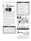
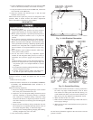
Fig. 11—Unit Electrical Connection
C00010
HIGH-VOLTAGE
POWER WIRING
ENTRY HOLE
LOW-VOLTAGE
WIRING ENTRY
HOLE
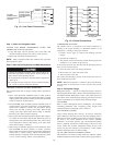
Fig. 12—Control Box Wiring
C00011
ELECTRIC
HEATER
FUSES
GROUND
LUG
INDOOR
FAN
RELAY
OUTDOOR FAN MOTOR
AND COMPRESSOR
START CAPACITOR
HIGH
VOLTAGE
LEADS
9