


NOTE: Be sure that all supply- and return-air grilles are open,
free from obstructions, and adjusted properly.
Disconnect electrical power to the unit and install lockout tag
before changing blower speed. Electrical shock can cause
serious injury or death.
Airflow can be changed by changing the lead connections of the
blower motor.
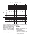
Units 50ZH024, 036, 048, and 060 blower motors are factory
wired for low speed operation. Units 50ZH030 and 042 are factory
wired for medium speed operation.
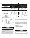
FOR 208/230-V
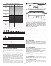
The motor leads are color-coded as follows:
To change the speed of the indoor fan motor (IFM), remove the fan
motor speed leg lead from the indoor fan relay (IFR) with units
024, 030, 042, 048 & 060 or the time delay relay (TDR) on 036
size and replace with lead for desired blower motor speed. Insulate
the removed lead to avoid contact with chassis parts.
FOR 460-V MOTORS
The motor leads are color coded as follows:
To change the speed of the indoor fan motor (IFM) from low speed
to high speed, remove the red lead from the indoor-fan relay (IFR).
ON 2–Speed Motors: Insulate the red lead to avoid contact with
any chassis parts. Separate the black lead from the purple lead.
Connect the black lead to the IFR. Insulate the purple lead to avoid
contact with any chassis parts. ON 3–Speed Motors: remove the
fan motor speed leg lead from the indoor (indoor) fan relay (IFR)
and replace with lead for desired blower motor speed.
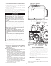
Step 5—Unit Controls
All compressors have the following internal-protection controls.
HIGH-PRESSURE RELIEF VALVE
This valve opens when the pressure differential between the low
and high side becomes excessive (024 size has temperature relief
only).
LOSS OF CHARGE SWITCH
Located on the outdoor liquid line is a low-pressure switch which
functions as a loss-of-charge switch. This switch contains a
Schrader core depressor. This switch opens at 7 psig and closes at
22 psig. No adjustment is necessary.
COMPRESSOR OVERLOAD
This overload interrupts power to the compressor when either the
current or internal temperature become excessive, and automati-
cally resets when the internal temperature drops to a safe level.
This overload may require up to 60 minutes (or longer) to reset;
therefore, if the internal overload is suspected of being open,
disconnect the electrical power to the unit and check the circuit
through the overload with an ohmmeter or continuity tester.
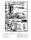
Step 6—Sequence of Operation
FAN OPERATION
The FAN switch on the thermostat controls indoor fan operation.
When the FAN switch is placed in the ON position, the IFR
(indoor-fan relay) is energized through the G terminal on the
thermostat. The normally-open contacts close, which then provide
power to the indoor (evaporator) fan motor (IFM). The IFM will
run continuously when the FAN switch is set to ON.
When the FAN switch is set to AUTO, the thermostat deenergizes
the IFR (provided there is not a call for cooling). The contacts open
and the IFM is deenergized. The IFM will be energized only when
there is a call for cooling, in heat pump heating mode or if the unit
is equipped with accessory electric heat, the indoor-fan motor will
also run while the accessory electric heat is energized.
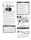
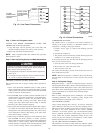
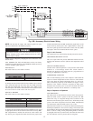
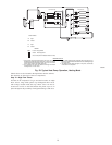
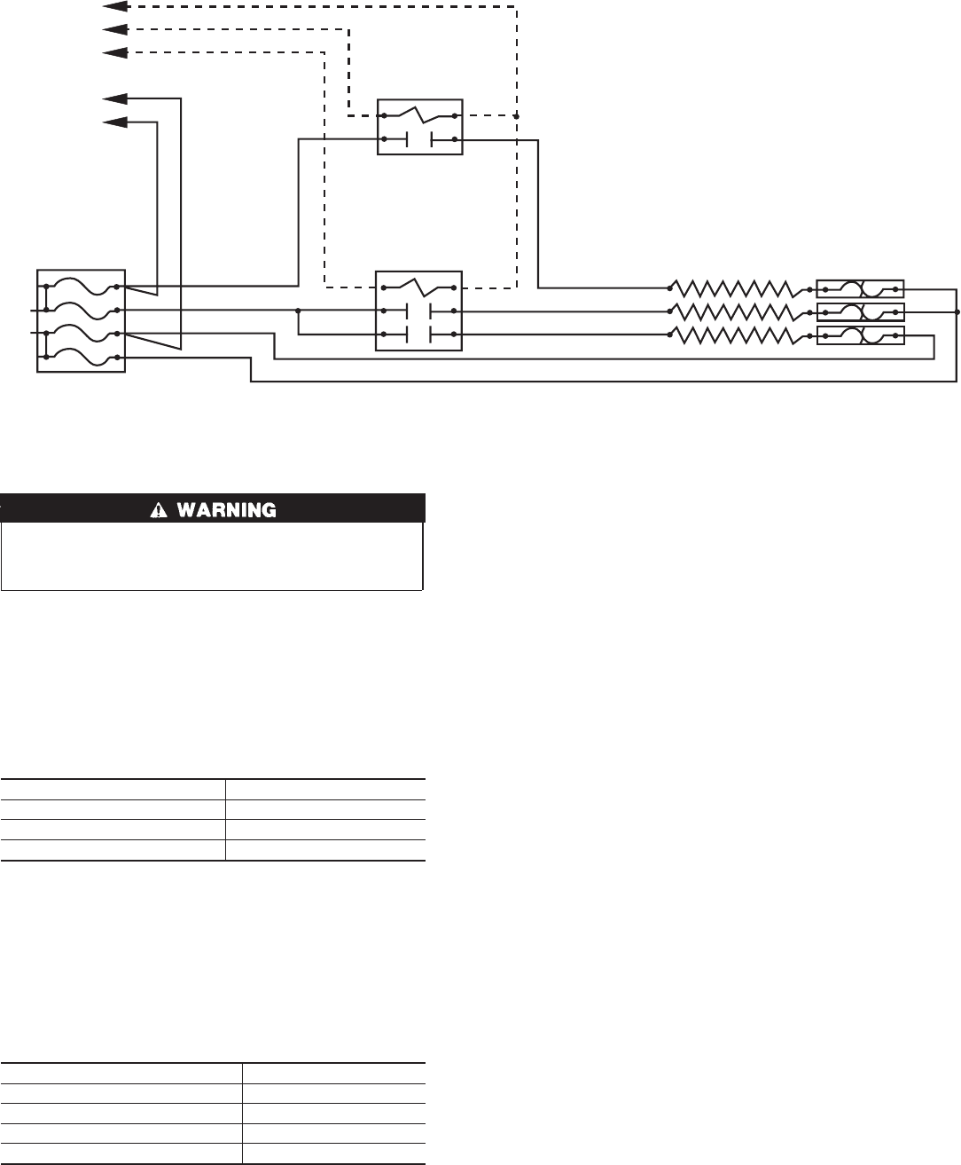
Fig. 15B—Accessory Electric Heater Wiring
C00014
C
W1
W1
TO
UNIT POWER
WIRING
BLK
YEL
BRN (COMMON)
VIO (STEP 2)
WHT ( STEP 1)
CONTACTOR 2
YEL
BRN
YEL
CONTACTOR 1
YEL
YEL
BRN
YEL
YEL
FUSE BLOCK
L2
L1
YEL
YEL
BLK
BLK
F3
F4
F1
F2
EL 1
EL 2
EL 3
BLK
BLK
BLK
AUTO-LIMIT
3-SPEED 2-SPEED
black = high speed black = high speed
blue = medium speed -
red = low speed red = low speed
3-SPEED (060 ONLY) 2-SPEED
black = high speed black = to purple
- yellow = line
orange = medium speed purple = to black
blue = low speed red = line
12