


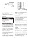

NOTE: Some units are equipped with a time-delay relay. On
these units, the indoor fan remains on for 30 seconds after G or Y
is deenergized.
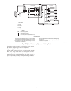
COOLING
With the thermostat subbase in the cooling position, the thermostat
makes circuit R-O. This energizes the reversing valve solenoid
(RVS) and places the unit in standby condition for cooling.
NOTE: The defrost control board has a 5 minute compressor
anti-short cycle time delay built in between compressor starts.
On a call for cooling, the compressor contactor (C) and the IFR are
energized through the Y and G terminals of the thermostat.
Energizing the compressor contactor supplies power to the com-
pressor and the outdoor (condenser) fan motor (OFM). Energizing
the IFR provides power to the IFM.
When the need for cooling has been satisfied, the OFM, compres-
sor, and IFM (FAN on AUTO) are deenergized. If the unit is
equipped with a 30-second delay (036 size only), the indoor fan
will remain energized for 30 seconds after the compressor is
deenergized. The reversing valve solenoid remains energized.
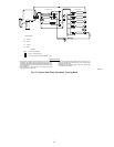
HEAT PUMP HEATING
On a call for heat, thermostat makes circuits R-Y and R-G. When
compressor time delay (5-minute ± 2 minutes) is completed, a
circuit is made to C, starting COMP and OFM. Circuit R-G also
energizes IFR and starts IFM after 1-second delay.
Should room temperature continue to fall, circuit R-W is made
through second-stage thermostat bulb. If optional electric heat
package is used, a relay is energized, bringing on first bank of
C99024
452=5v
457=7v
455=2v
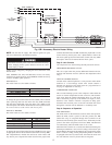
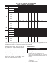
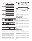
LEGEND
FLA — Full Load Amps
LRA — Locked Rotor Amps
MCA — Minimum Circuit Amps
MOCP — Maximum Overcurrent Protection
RLA — Rated Load Amps
NOTES:
1. In compliance with NEC (National Electrical Code) requirements
for multimotor and combination load equipment (refer to NEC
Articles 430 and 440), the overcurrent protective device for the
unit shall be Power Supply fuse. Canadian units may be
fuse or circuit breaker.
2. Minimum wire size is based on 60 C copper wire. If other than
60 C wire is used, or if length exceeds wire length in table,
determine size from NEC.
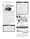
3. Unbalanced 3-Phase Supply Voltage
Never operate a motor where a phase imbalance in supply volt-
age is greater than 2%.
Use the following formula to determine
the percentage of voltage imbalance.
% Voltage imbalance
max voltage deviation from average voltage
= 100 x
average voltage
EXAMPLE: Supply voltage is 460-3-60.
AB = 452 v
BC = 464 v
AC = 455 v
452 + 464 + 455
Average Voltage =
3
1371
=
3
= 457
Determine maximum deviation from average voltage.
(AB) 457
(BC) 464
(AC) 457
Maximum deviation is 7 v.
Determine percent of voltage imbalance.
7
% Voltage Imbalance = 100 x
457
= 1.53%
This amount of phase imbalance is satisfactory as it is below the
maximum allowable 2%.
IMPORTANT: If the supply voltage phase imbalance is
more than 2%, contact your local electric utility company
immediately.
®
CKT BKR
—
Circuit Breaker
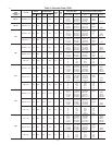
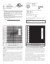
758 110
683 100
621 90
552 80
483 70
414 60
345 50
276 40
207 30
30 40 50 60 70 80 90
-1 41016212732
SUCTION LINE TEMPERATURE (
O
F)
SUCTION LINE TEMPERATURE (
O
C)
OUTDOOR TEMP
O
F
O
C
115 46
105 41
95 35
85 29
75 24
65 18
55 13
45 7
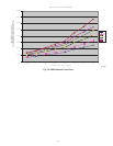
SUCTION LINE PRESSURE (KILOPASCALS)
SUCTION LINE PRESSURE (PSIG)
C00162
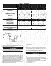
Fig. 16—Cooling Charging Chart, 50ZH024 Units
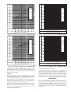
758 110
683 100
621 90
552 80
483 70
414 60
345 50
276 40
207 30
30 40 50 60 70 80 90
-1 41016212732
SUCTION LINE TEMPERATURE (
O
F)
SUCTION LINE TEMPERATURE (
O
C)
SUCTION LINE PRESSURE (KILOPASCALS)
SUCTION LINE PRESSURE (PSIG)
OUTDOOR TEMP
O
F
O
C
115 46
105 41
95 35
85 29
75 24
65 18
55 13
45 7
C00163
Fig. 17—Cooling Charging Chart, 50ZH030
14