


supplemental electric heat. When thermostat is satisfied, contacts
open, deenergizing contactor and relay; motors and heaters deen-
ergize. The IFM may be controlled by a time-delay relay that keeps
the fan on for 30 seconds.
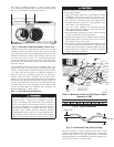
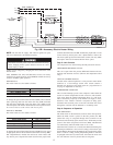
DEFROST
Defrost board (DB) is a time and temperature control, which
includes a field-selectable time period between checks for defrost
(30, 50 and 90 minutes). The time period is factory-set at 30
minutes and should only be adjusted by a trained service person.
Electronic timer and defrost cycle start only when contactor is
energized and defrost thermostat (DFT) is closed.
Defrost mode is identical to Cooling mode. The outdoor fan motor
stops because of “OF1” and “OF2” contacts opening on the defrost
board, a bank of optional electric heat turns on to warm air
supplying the conditioned space.
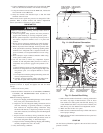
ELECTRIC RESISTANCE HEATING
If accessory electric heaters are installed, on a call for “Emergency
Heat” the thermostat energizes W which energises the heater relay
and in turn energizes the electric heaters. The IFR is energized
which starts the indoor-fan motor. If the heaters are staged, W2 is
energized when the second stage of heating is required. When the
need for heating is satisfied, the heater and IFM are deenergized.
MAINTENANCE
To ensure continuing high performance, and to reduce the possi-
bility of premature equipment failure, periodic maintenance must
be performed on this equipment. This cooling unit should be
inspected at least once each year by a qualified service person. To
troubleshoot cooling of units, refer to Troubleshooting chart in
back of book.
758 110
683 100
621 90
552 80
483 70
414 60
345 50
276 40
207 30
30 40 50 60 70 80 90
-1 41016212732
SUCTION LINE TEMPERATURE (
O
F)
SUCTION LINE TEMPERATURE (
O
C)
SUCTION LINE PRESSURE (KILOPASCALS)
SUCTION LINE PRESSURE (PSIG)
OUTDOOR TEMP
O
F
O
C
115 46
105 41
95 35
85 29
75 24
65 18
55 13
45 7
C00164
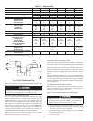
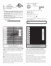
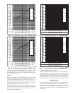
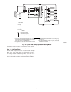
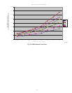
Fig. 18—Cooling Charging Chart, 50ZH036 Units
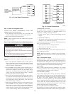
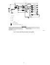
Fig. 19—Cooling Charging Chart, 50ZH042 Units
C00165
758 110
683 100
621 90
552 80
483 70
414 60
345 50
276 40
207 30
30 40 50 60 70 80 90
-1 41016212732
SUCTION LINE TEMPERATURE (
O
F)
SUCTION LINE TEMPERATURE (
O
C)
SUCTION LINE PRESSURE (KILOPASCALS)
SUCTION LINE PRESSURE (PSIG)
OUTDOOR TEMP
O
F
O
C
115 46
105 41
95 35
85 29
75 24
65 18
55 13
45 7
758 110
683 100
621 90
552 80
483 70
414 60
345 50
276 40
207 30
30 40 50 60 70 80 90
-1 41016212732
SUCTION LINE TEMPERATURE (
O
F)
SUCTION LINE TEMPERATURE (
O
C)
SUCTION LINE PRESSURE (KILOPASCALS)
SUCTION LINE PRESSURE (PSIG)
OUTDOOR TEMP
O
F
O
C
115 46
105 41
95 35
85 29
75 24
65 18
55 13
45 7
C00166
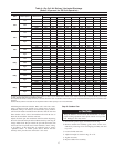
Fig. 20—Cooling Charging Chart, 50ZH048 Units
758 110
683 100
621 90
552 80
483 70
414 60
345 50
276 40
207 30
30 40 50 60 70 80 90
-1 41016212732
SUCTION LINE TEMPERATURE (
O
F)
SUCTION LINE TEMPERATURE (
O
C)
SUCTION LINE PRESSURE (KILOPASCALS)
SUCTION LINE PRESSURE (PSIG)
OUTDOOR TEMP
O
F
O
C
115 46
105 41
95 35
85 29
75 24
65 18
55 13
45 7
C00167
Fig. 21—Cooling Charging Chart, 50ZH060 Units
15