


Step 1—Check for Refrigerant Leaks
LOCATE AND REPAIR REFRIGERANT LEAKS AND
CHARGE THE UNIT AS FOLLOWS:
1. Using both high- and low-pressure ports, locate leaks and
reclaim remaining refrigerant to relieve system pressure.
2. Repair leak following accepted practices.
NOTE: Install a liquid-line filter drier whenever the system has
been opened for repair.
Step 2—Start-Up Cooling Section and Make Adjustments
Complete the required procedures given in the Pre-Start- Up
section this page before starting the unit. Do not jumper any
safety devices when operating the unit.
Do not operate the compressor when the outdoor temperature
is below 40 F.
Do not rapid-cycle the compressor. Allow 5 minutes between
‘‘on’’ cycles to prevent compressor damage.
CHECKING COOLING CONTROL OPERATION
Start and check the unit for proper cooling control operation as
follows:
1. Place room thermostat SYSTEM switch in OFF position.
Observe that blower motor starts when FAN switch is placed
in ON position and shuts down within 30 seeconds when FAN
switch is placed in AUTO position.
2. Place SYSTEM switch in COOL position and FAN switch in
AUTO position. Set cooling control below room temperature.
Observe that compressor, outdoor fan, and indoor blower
motors start and that reversing valve shifts. Observe that
cooling cycle shuts down when control setting is satisfied.
Reversing valve (RV) remains energized.
3. Place system switch in HEAT position. Observe that compres-
sor, indoor fan and outdoor fan energize (Reversing Valve is
deenergized in heat pump heating mode). Set control above
room temperature. Observe that heating cycle shuts down
when control setting is satisfied.
4. When using an automatic changeover room thermostat, place
both SYSTEM and FAN switches in AUTO. positions.
Observe that unit operates in Cooling mode when temperature
control is set to ‘‘call for cooling’’ (below room temperature),
and unit operates in Heating mode when temperature control
is set to “call for heating” (above room temperature).
COMPRESSOR ROTATION
On 3–Phase units it is important to be certain compressor is
rotating in the proper direction. To determine whether or not
compressor is rotating in the proper direction:
1. Connect service gages to suction and discharge pressure
fittings.
2. Energize the compressor.
3. The suction pressure should drop and the discharge pressure
should rise, as is normal on any start-up.
If the suction pressure does not drop and the discharge pressure
does not rise to normal levels:
1. Turn off power to the unit and tag disconnect.
2. Reverse any two of the unit power leads.
3. Turn on power to the unit.
The suction and discharge pressure levels should now move to
their normal start-up levels.
NOTE: When the compressor is rotation in the wrong direction,
the unit makes an elevated level of noise and does not provide
cooling.
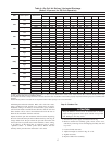
Step 3—Refrigerant Charge
Refrigerant Charge — Amount of refrigerant charge is listed on
unit nameplate and in Table 1. Refer to Carrier Refrigerant Service
Techniques Manual, Refrigerants section. Unit panels must be in
place when unit is operating during charging procedure. Unit must
operate a minimum of 15 minutes before checking charge.
NO CHARGE
Refer to Carrier Refrigerant Service Techniques. Use standard
evacuating techniques. After evacuating system, weigh in the
specified amount of refrigerant (refer to Table 1).
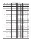
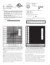
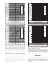
LOW CHARGE COOLING
Using cooling charging chart (see Fig. 16–21),Vary refrigerant
until conditions of the chart are met. Note that charging chart is
different from those normally used. Charts are based on charging
the units to the correct superheat for the various operating
conditions. An accurate pressure gage and temperature-sensing
device is required. Connect the pressure gauge to the service port
on the suction line. Connect temperature sensing device to the
suction line near the compressor and insulate it so that outdoor
ambient temperature does not affect reading.
TO USE THE COOLING CHARGING CHART
This method is to be used in cooling mode only. Take the outdoor
ambient temperature and read the suction pressure gauge. Refer to
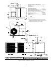
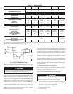
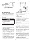
3-PHASE
CONNECTIONS
TO DISCONNECT
PER NEC
SINGLE-PHASE
CONNECTIONS
TO DISCONNECT
PER NEC
GROUND
LEAD
UNIT GROUND
BLK
YEL
BLU
L
L
L
C00012
Fig. 13—Line Power Connections
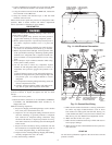
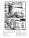
Y
C
W2
E
G
R
O
THERMOSTAT
AND SUBBASE
UNIT CONTROL POWER
SPLICE BOX
BRN
WHT
YEL
GRN
RED
ORN
C99056
Fig. 14—Control Connections
10