


Unit removes condensate through a 1 3/64-in. ID hole (using
3/4-in. OD piping or tubing) which is located at the end of the unit.
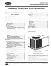
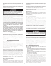
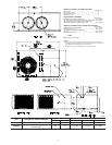
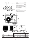
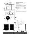
See Fig. 2-4 for location of condensate connection.
Condensate water can be drained directly onto the roof in rooftop
installations (where permitted) or onto a gravel apron in ground-
level installations. Install a field-supplied condensate trap at end of
condensate connection to ensure proper drainage. Make sure that
the outlet of the trap is at least 1 in. lower than the drain-pan
condensate connection to prevent the pan from overflowing. Prime
the trap with water. When using a gravel apron, make sure it slopes
away from the unit.
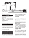
If the installation requires draining the condensate water away
from the unit, install a 2-in. trap using a 3/4-in. OD tubing or pipe.
(See Fig. 9 and 10.) Make sure that the outlet of the trap is at least
1 in. lower than the unit drain-pan condensate connection to
prevent the pan from overflowing. Prime the trap with water.
Connect a drain tube using a minimum of 3/4-in. PVC, 3/4-in.
CPVC, or 3/4-in. copper pipe (all field supplied). Do not undersize
the tube. Pitch the drain tube downward at a slope of at least 1 in.
for every 10 ft of horizontal run. Be sure to check the drain tube
for leaks. Prime trap at the beginning of the cooling season
start-up. Allowable glues for condensate trap connection are:
Standard ABS, CPVC, or PVC cement.
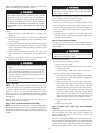
Step 7—Install Electrical Connections
The unit cabinet must have an uninterrupted, unbroken
electrical ground to minimize the possibility of personal
injury if an electrical fault should occur. This ground may
consist of an electrical wire connected to the unit ground in
the control compartment, or conduit approved for electrical
ground when installed in accordance with NEC (National
Electrical Code), ANSI (American National Standards
Institute)/NFPA (latest edition) (in Canada, Canadian Elec-
trical Code CSA C22.1) and local electrical codes. Failure to
adhere to this warning could result in serious injury or death.
Failure to follow these precautions could result in damage to
the unit being installed:
1. Make all electrical connections in accordance with NEC
ANSI/NFPA (latest edition) and local electrical codes
governing such wiring. In Canada, all electrical connec-
tions must be in accordance with CSA standard C22.1
Canadian Electrical Code Part 1 and applicable local
codes. Refer to unit wiring diagram.
2. Use only copper conductor for connections between
field-supplied electrical disconnect switch and unit. DO
NOT USE ALUMINUM WIRE.
3. Be sure that high-voltage power to unit is within operating
voltage range indicated on unit rating plate.
4. Insulate low-voltage wires for highest voltage contained
within conduit when low-voltage control wires are run in
same conduit as high-voltage wires.
5. Do not damage internal components when drilling through
any panel to mount electrical hardware, conduit, etc. On
3-phase units, ensure phases are balanced within 2 percent.
Consult local power company for correction of improper
voltage and/or phase imbalance.
HIGH-VOLTAGE CONNECTIONS
The unit must have a separate electrical service with a field-
supplied, waterproof disconnect switch mounted at, or within sight
from the unit. Refer to the unit rating plate for maximum
fuse/circuit breaker size and minimum circuit amps (ampacity) for
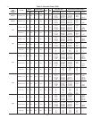
wire sizing. See Table 3 for electrical data.
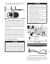
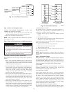
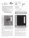
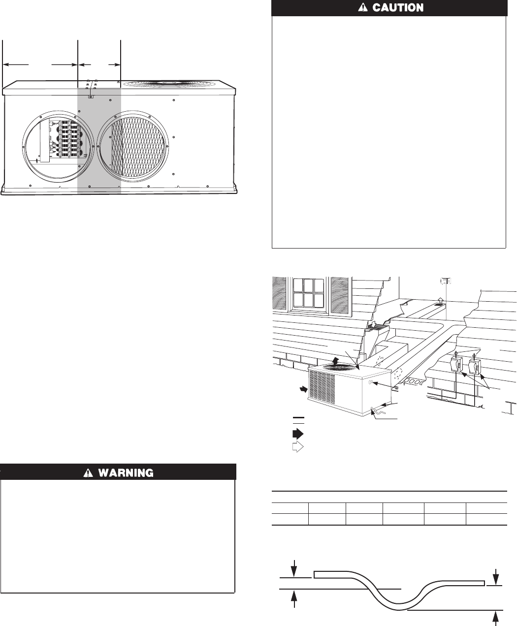
Fig. 7—Area Not to Be Drilled More Than 3/4-in.
C00007
19.17″ 3.92″
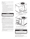
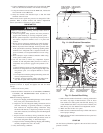
Fig. 8—Typical installation
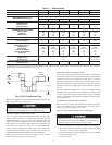
Table 2—Minimum Airflow for Safe Electric Heater
Operation (CFM)
SIZE
024 030 036 042 048 060
600 750 900 1050 1200 1500
C00008
C00008
TOP COVER
INDOOR
THERMOSTAT
DISCONNECT
PER NEC*
(UNIT AND
ELECTRIC
HEATER)
FROM
POWER
SOURCE
RETURN
AIR
POWER AND
LOW-VOLTAGE
ENTRY
COMPOSITE
RUST-PROOF
BASEPAN
CONDENSATE
DRAIN
CONNECTION
*Separate disconnect per NEC
(National Electrical Code) required
for electric heater when single-
point conection is not used.
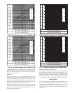
Power Wiring
Control Wiring
Condenser Airflow
Evaporator Airflow
Fig. 9—Condensate Trap (Using Tubing)
C99013
1” (25mm) MIN.
2” (50mm) MIN.
TRAP
OUTLET
7