


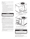

INSTALL FLANGES FOR DUCTWORK CONNECTIONS
(50ZH060 ONLY)
The 50ZH060 units are shipped with flanges which must be
field-installed on the unit.
To install unit flanges:
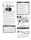
1. Five pieces of flange are shipped on the return-air opening of
the unit. Remove the flanges from the shipping position (See
Fig. 5). Screws are field-supplied.
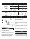
2. One piece of flange is used as it is shipped (straight). Bend the
other 4 pieces at right angles.
3. Install the straight flange on the right side of the return-air
opening in holes provided. (See Fig. 6). Flanges should stick
out from unit to allow for connection of ductwork.
4. Install 2 hand-formed flanges onto return air opening in holes
provided to form a rectangle around the return air opening.
5. Install remaining 2 hand-formed flanges around discharge air
opening in holes provided.
6. Ductwork can now be attached to flanges.
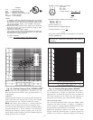
When designing and installing ductwork, consider the following:
When connecting ductwork to units, do not drill deeper than
3/4 inch in shaded area shown in Fig. 7 or coil may be
damaged.
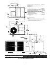
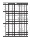
• All units should have field-supplied filters installed in the
return-air side of the unit. Recommended sizes for filters are
shown in Table 1.
• Avoid abrupt duct size increases and reductions. Abrupt change
in duct size adversely affects air performance.
IMPORTANT: Use flexible connectors between ductwork and
unit to prevent transmission of vibration. Use suitable gaskets to
ensure weathertight and airtight seal. When electric heat is
installed, use fire proof canvas (or similar heat resistant material)
connector between ductwork and unit discharge connection. If
flexible duct is used, insert a sheet metal sleeve inside duct. Heat
resistant duct connector (or sheet metal sleeve) must ectend 24–in.
from the unit discharge connection flange into the ductwork.
• Size ductwork for cooling air quantity (cfm). The minimum air
quantity for proper electric heater operation is listed in Table 2.
Heater limit switches may trip at air quantities below those
recommended.
• Insulate and weatherproof all external ductwork. Insulate and
cover with a vapor barrier all ductwork passing through
conditioned spaces. Follow latest Sheet Metal and Air Condi-
tioning Contractors National Association (SMACNA) and Air
Conditioning Contractors Association (ACCA) minimum in-
stallation standards for residential heating and air conditioning
systems.
• Secure all ducts to building structure. Flash, weatherproof, and
vibration-isolate duct openings in wall or roof according to
good construction practices.
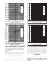
Figure 8 shows a typical duct system with 50ZH unit installed.
CONVERTING HORIZONTAL DISCHARGE UNITS TO
DOWNFLOW (VERTICAL) DISCHARGE
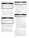
Before performing service or maintenance operations on
system, turn off main power to unit and install lockout tag.
Turn off accessory heater power switch if applicable. Elec-
trical shock can cause serious injury or death.
Units are dedicated side supply products. They are not convertible
to vertical air supply. A field-supplied plenum must be used to
convert to vertical air discharge.
Step 6—Provide for Condensate Disposal
NOTE: Be sure that condensate-water disposal methods comply
with local codes, restrictions, and practices.
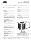
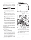
Fig. 5—Shipping Location of Duct Flanges
(Size 060 Only)
C00005
FIVE PIECES OF DUCT
FLANGE ATTACHED
HERE FOR SHIPMENT
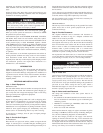
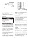
Fig. 6—Flanges Installed on 50ZH060 Units
C00006
HAND
FORM
HAND FORM
STRAIGHT PIECE
6