


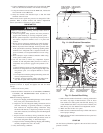

The field-supplied disconnect may be mounted on the unit over the
high-voltage inlet hole. See Fig. 2-4.
Operation of unit on improper line voltage constitutes abuse
and may cause unit damage that could affect warranty.
ROUTING POWER LEADS INTO UNIT
Use only copper wire between disconnect and unit. The high-
voltage leads should be in a conduit until they enter the unit;
conduit termination at the unit must be watertight. Run the
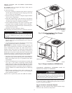
high-voltage leads through the hole on the control box side of the
unit (see Fig. 11 for location). When the leads are inside the unit,
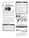
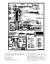
run leads to the control box (Fig. 12). For single-phase units,
connect leads to the black and yellow wires; for 3-phase units,
connect the leads to the black, yellow, and blue wires (see Fig. 13).
CONNECTING GROUND LEAD TO UNIT GROUND
Refer to Fig. 12 and 13. Connect the ground lead to the chassis
using the unit ground lug in the control box.
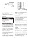
ROUTING CONTROL POWER WIRES
Form a drip-loop with the thermostat leads before routing them
into the unit. Route the thermostat leads through grommeted hole
provided in unit into unit control box (See Fig. 11). Connect
thermostat leads and unit power leads as shown in Fig. 13 & 14.
Route thermostat wires through grommet providing a drip-loop at
the panel. Connect low-voltage leads to the thermostat as shown in
Fig. 14.
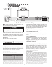
The unit transformer supplies 24-v power for complete system
including accessory electrical heater. Transformer is factory wired
for 230-v operation. If supply voltage is 208 v, rewire transformer
primary as described in the Special Procedures for 208-v Opera-
tion section below.
ACCESSORY ELECTRIC HEAT WIRING
Refer to accessory electric heat installation instructions for infor-
mation on installing accessory electric heat. Accessory electric
heat wiring is shown in Fig. 15A & 15B.
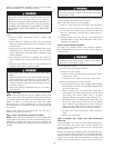
SPECIAL PROCEDURES FOR 208-V OPERATION
Make sure that the power supply to the unit is switched OFF
and install lockout tag before making any wiring changes.
Electrical shock can cause serious injury or death.
1. Remove wirenut from connection of ORG wire to BLK wire.
Disconnect the ORG transformer-primary lead from the BLK
wire. Save wirenut. See unit wiring label.
2. Remove the wirenut from the terminal on the end of the RED
transformer-primary lead.
3. Save the wirenut.
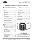
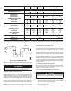
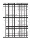
Table 1 — Physical Data
UNIT 50ZH 024 030 036 042 048 060
OPERATING WEIGHT (lbs) 232 254 277 295 328 368
COMPRESSOR TYPE Scroll
REFRIGERANTCharge(lb)
R-22
3.7 5.85.96.69.19.7
REFRIGERANT METERING DEVICE Acutrol™ System
OUTDOOR COIL
Rows...Fins/in.
Face Area (sq ft)
Copper Tubes, Aluminum Plate Fins
1...17
7.9
2...17
6.7
1...17
11.1
2...17
9.3
2...17
11.1
2...17
12.7
OUTDOOR-FAN MOTOR CFM
Nominal Rpm
Motor Hp
Diameter (in.)
Propeller
1800
825
1/8
20
2000
1100
1/4
20
2600
1100
1/4
20
2600
1100
1/4
20
2600
1100
1/4
20
3200
1100
1/2
20
INDOOR COIL Copper Tubes, Aluminum Plate Fins
Rows...Fins/in.
Face Area (sq ft)
2...15
3.1
3...15
3.1
3...15
4.0
3...15
4.0
4...15
4.4
4...15
4.9
INDOOR FAN MOTOR
Blower Motor Size (in.)
Nominal Cfm
Rpm Range
Number of Speeds
Factory Speed Setting
Motor Hp
Direct Drive
10x8
800
550-1000
3
Low
1/4
10x8
1000
550-1000
3
Med
1/4
10x9
1200
800-1050
3
Low
1/2
10x9
1400
800-1050
3
Med
1/2
10x9
1600
1000-1100
2
Low
3/4
10x10
2000
950-1100
3
Low
1
CONNECTING DUCT SIZES
Supply Air (in.)
Return Air (in.)
Round
14
14
Square
13.9 x 13.9
13.9 x 27.8
FIELD-SUPPLIED RETURN-AIR FILTER†
Throwaway (in.)
24x24 24x24 24x24 24x24 24x30 24x30
* 460-v motors are 2-speed or 3-speed.
†Required filter sizes shown are based on the ARI (Air Conditioning and Refrigeration Institute) rated airflow at a velocity of 300 ft/min for throwaway type or 450 ft/min
for high capacity type. Recommended filters are 1-in. thick.
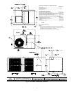
Fig. 10–PVC Condensate Trap
C00009
TRAP
OUTLET
2" min.
1" min.
8