


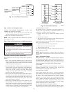

Step 6—Electrical Controls and Wiring
Inspect and check the electrical controls and wiring annually. Be
sure to turn off the electrical power to the unit and install lockout
tag.
Remove the top panel to locate all the electrical controls and
wiring. Check all electrical connections for tightness. Tighten all
screw connections. If any smoky or burned connections are
noticed, disassemble the connection, clean all the parts, restrip the
wire end and reassemble the connection properly and securely.
Check to ensure no wires are touching refrigerant tubing or sharp
sheet metal edges. Move and secure wires to isolate from tubing
and sheet metal edges.
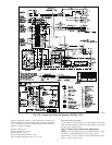
After inspecting the electrical controls and wiring, replace all the
panels. Start the unit, and observe at least one complete cooling
cycle to ensure proper operation. If discrepancies are observed in
operating cycle, or if a suspected malfunction has occurred, check
each electrical component with the proper electrical instrumenta-
tion. Refer to the unit wiring label when making these checkouts.
NOTE: Refer to the Sequence of Operation section, as an aid in
determining proper control operation.
Step 7—Refrigerant Circuit
Inspect all refrigerant tubing connections and the unit base for oil
accumulations annually. Detecting oil generally indicates a refrig-
erant leak.
If oil is detected or if low cooling performance is suspected,
leak-test all refrigerant tubing using an electronic leak-detector, or
liquid-soap solution. If a refrigerant leak is detected, refer to Check
for Refrigerant Leaks section. (See Table of Contents for page
number.)
If no refrigerant leaks are found and low cooling performance is
suspected, refer to Refrigerant Charge. (See Table of Contents for
page number.)
Step 8—Indoor Airflow
The cooling airflow does not require checking unless improper
performance is suspected. If a problem exists, be sure that all
supply- and return-air grilles are open and free from obstructions,
and that the air filter is clean. When necessary, refer to Indoor
Airflow and Airflow Adjustments section to check the system
airflow.
Step 9—Metering Devices
Refrigerant metering devices are fixed orifices and are located in
the inlet header to the indoor and outdoor coils.
Check valves are also located in the liquid lines near the strainers.
The check valves are the smaller of the two components.
Step 10—Lubrication
COMPRESSOR—The compressor is charged with the correct
amount of oil at the factory.
FAN MOTOR BEARINGS—Fan motor bearings are perma-
nently lubricated. No further lubrication of outdoor or indoor fan
motors is required.
Step 11—Liquid Line Strainer
The liquid line strainer (to protect metering device) is made of wire
mesh and is located in the liquid line on the inlet side of the
metering device.
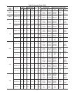
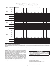
Table 5—Wet Coil Pressure Drop
UNIT SIZE
50ZH
AIRFLOW
(CFM)
PRESSURE DROP
(IN. WG)
024
600 0.02
700 0.05
800 0.06
900 0.07
030
900 0.06
1000 0.06
1200 0.08
036
1000 0.07
1200 0.09
1400 0.11
1600 0.12
042
1000 0.04
1200 0.06
1400 0.08
1600 0.09
048
1400 0.07
1600 0.08
1800 0.09
060
1700 0.07
1800 0.08
2100 0.09
2300 0.10
Table 6—Filter Pressure Drop (in. wg)
UNIT
SIZE
50ZH
FILTER
SIZE
(IN.)
CFM
500 600 700 800 900 1000 1100 1200 1300 1400
024-042 24 x 24 0.06 0.07 0.08 0.08 0.09 0.09 0.09 0.10 0.11 0.12
048, 060 24x30------ - -0.08 0.09
UNIT
SIZE
50ZH
FILTER
SIZE
(IN.)
CFM
1500 1600 1700 1800 1900 2000 2100 2200 2300
024-042 24 x 24 0.14 0.15 -------
048,060 24 x 30 0.10 0.11 0.12 0.13 0.14 0.15 0.16 0.17 0.18
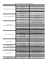
Table 7—Accessory Electric Heat Pressure Drop
(in. wg)
HEATER KW
5-20
CFM
600 800 1000 1200 1400 1600 1800 2000 2200
0.06 0.08 0.10 0.13 0.15 0.18 0.20 0.23 0.25
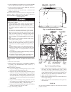
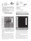
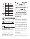
Fig. 21—Outdoor-Fan Adjustment (024–048 Size)
C00021
3.125 in.
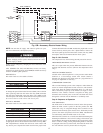
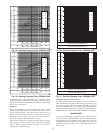
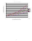
Fig. 22—Outdoor-Fan Adjustment (060 Size)
C02017
0.708in.
18