


5
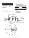
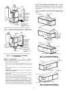
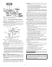
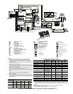
NOTES:
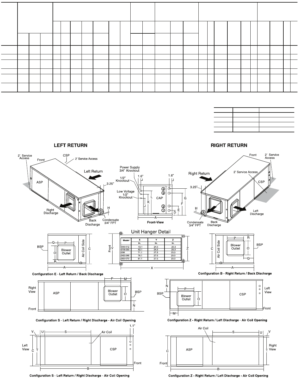
1. Condensate is
3
/
4
-in. FPT copper.
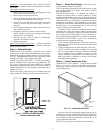
2. Horizontal unit shipped with filter bracket only. This bracket should be
removed for return duct connection.
3. Discharge flange and hanger kit is factory installed.
4. Shaded areas are recommended service areas, not required.
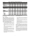
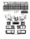
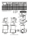
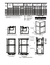
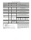
50PSH
UNIT
SIZE
OVERALL
CABINET
(in.)
WATER CONNECTIONS
(in.)
WATER
CONNEC-
TIONS (in.) -
UNITS WITH
HWR
ELECTRICAL
KNOCKOUTS
(in.)
DISCHARGE CONNECTION (in.)
DUCT FLANGE INSTALLED
(±0.10 in.)
RETURN
CONNECTION (in.)
USING RETURN
AIR OPENING
(±0.10 in.)
12 3 4 5
Loop
Water
FPT
HWG
FPT
12
J
1
/
2
Cond
K
1
/
2
Cond
L
3
/
4
Cond
M
(LH
rtrn)
NO
Supply
Height
P
Supply
Width
Q
(RH
rtrn)
RS
Return
Depth
T
Return
Height
UV
A
Width
B
Depth
C
Height
D
In
E
Out
F
HWG
In
G
HWG
Out
H
Con-
densate
Loop
In D
Loop
Out E
Low
Voltage
Ext
Pump
Power
Supply
006,009,
012
22.4 43.1 17.3 3.7 9.7 N/A N/A 0.8
1
/
2
N/A N/A N/A 3.8 6.3 8.8 5.3 4.1 9.0 9.0 5.3 4.1 17.1 15.3 2.1 1.0
018 22.4 62.2 19.3 2.1 10.0 13.9 16.9 0.6
3
/
4
1
/
2
2.1 10.0 3.6 6.1 8.6 3.6 2.0 12.5 15.5 3.6 2.0 28.1 16.2 2.3 1.5
024,
030
22.4 62.2 19.3 2.1 10.0 13.9 16.9 0.6
3
/
4
1
/
2
5.26 13.13 3.6 6.1 8.6 3.6 2.0 12.5 15.5 3.6 2.0 33.8 16.2 2.3 1.5
036 25.4 71.2 21.3 3.4 10.8 15.6 18.9 0.6
3
/
4
1
/
2
5.96 13.13 3.6 6.1 8.6 3.1 1.2 19.0 17.5 3.1 1.0 34.8 18.2 3.1 1.5
042,
048
25.4 76.2 21.3 3.4 10.8 15.6 18.9 0.6 1
1
/
2
5.96 13.13 3.6 6.1 8.6 3.1 1.2 19.0 17.5 3.1 1.0 39.8 18.2 3.1 1.5
060,
070
25.4 81.2 21.3 3.4 10.8 15.6 18.9 0.6 1
1
/
2
5.96 13.13 3.6 6.1 8.6 3.1 1.2 19.0 17.5 3.1 1.0 44.8 18.2 3.1 1.5
a50-8231
PSC BLOWER AIRFLOW
CONFIGURATION
CODE RETURN DISCHARGE
E Left Back
B Right Back
S Left Right
Z Right Left
LEGEND
ASP — Alternate Service Panel
BSP — Blower Service Panel
CAP — Control Access Panel
CSP — Compressor Service Panel
FPT — Female Pipe Thread
HWG — Hot Water Generator
HWR — Hot Water Reheat
LH — Left Hand
RH — Right Hand
Fig. 2 — 50PSH Dimensional Data