


29
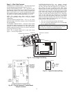
3. Wire each terminal on the sensor to the same terminal on
the controller. See Fig. 15-25. Table 10 shows the recom-
mended Rnet wiring scheme.
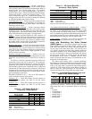
Table 10 — Rnet Wiring
NOTE: The wire should be connected to the terminal shown.
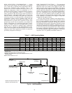
Wiring a Supply Air Temperature (SAT) Sensor — The
SAT sensor is required for reheat applications.
If the cable used to wire the SAT sensor to the controller
will be less than 100 ft, an unshielded 22 AWG (American
Wire Gage) cable should be used. If the cable will be greater
than 100 ft, a shield 22 AWG cable should be used. The cable
should have a maximum length of 500 ft.
To wire the SAT sensor to the controller:
1. Wire the sensor to the controller. See Fig. 15-25.
2. Verify that the Enable SAT jumper is on.
3. Verify that the Enable SAT and Remote jumper is in the
left position.
Wiring an Indoor Air Quality (IAQ) Sensor
— An IAQ
sensor monitors CO
2
levels. The WSHP Open controller uses
this information to adjust the outside-air dampers to provide
proper ventilation. An IAQ sensor can be wall-mounted or
mounted in a return air duct. (Duct installation requires an aspi-
rator box assembly.)
The sensor has a range of 0 to 2000 ppm and a linear 4 to
20 mA output. This is converted to 1 to 5 vdc by a 250-ohm,
1
/
4
watt, 2% tolerance resistor connected across the zone con-
troller’s IAQ input terminals.
NOTE: Do not use a relative humidity sensor and CO
2
sensor
on the same zone controller if both sensors are powered off the
board. If sensors are externally powered, both sensors may be
used on the same zone controller.
If the cable used to wire the IAQ sensor to the controller
will be less than 100 ft, an unshielded 22 AWG (American
Wire Gage) cable should be used. If the cable will be greater
than 100 ft, a shield 22 AWG cable should be used. The cable
should have a maximum length of 500 ft.
To wire the IAQ sensor to the controller:
1. Wire the sensor to the controller. See Fig. 15-25.
2. Install a field-supplied 250-ohm,
1
/
4
watt, 2% tolerance
resistor across the controller’s RH/IAQ and Gnd
terminals.
3. Verify the the RH/IAQ jumper is set to 0 to 5 vdc.
Wiring a Relative Humidity (RH) Sensor
— The RH sensor
is used for zone humidity control (dehumidification) if the
WSHP unit has a dehumidification device. If not, the sensor
only monitors humidity.
NOTE: Do not use a relative humidity sensor and CO
2
sensor
on the same zone controller if both sensors are powered off the
board. If sensors are externally powered, both sensors may be
used on the same zone controller.
If the cable used to wire the RH sensor to the controller will
be less than 100 ft, an unshielded 22 AWG (American Wire
Gage) cable should be used. If the cable will be greater than
100 ft, a shield 22 AWG cable should be used. The cable
should have a maximum length of 500 ft.
To wire the RH sensor to the controller:
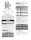
1. Strip the outer jacket from the cable for at least 4 in.
2. Strip
1
/
4
in. of insulation from each wire.
3. Wire the sensor to the controller.
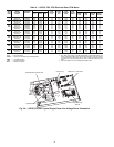
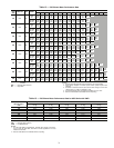
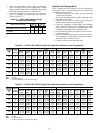
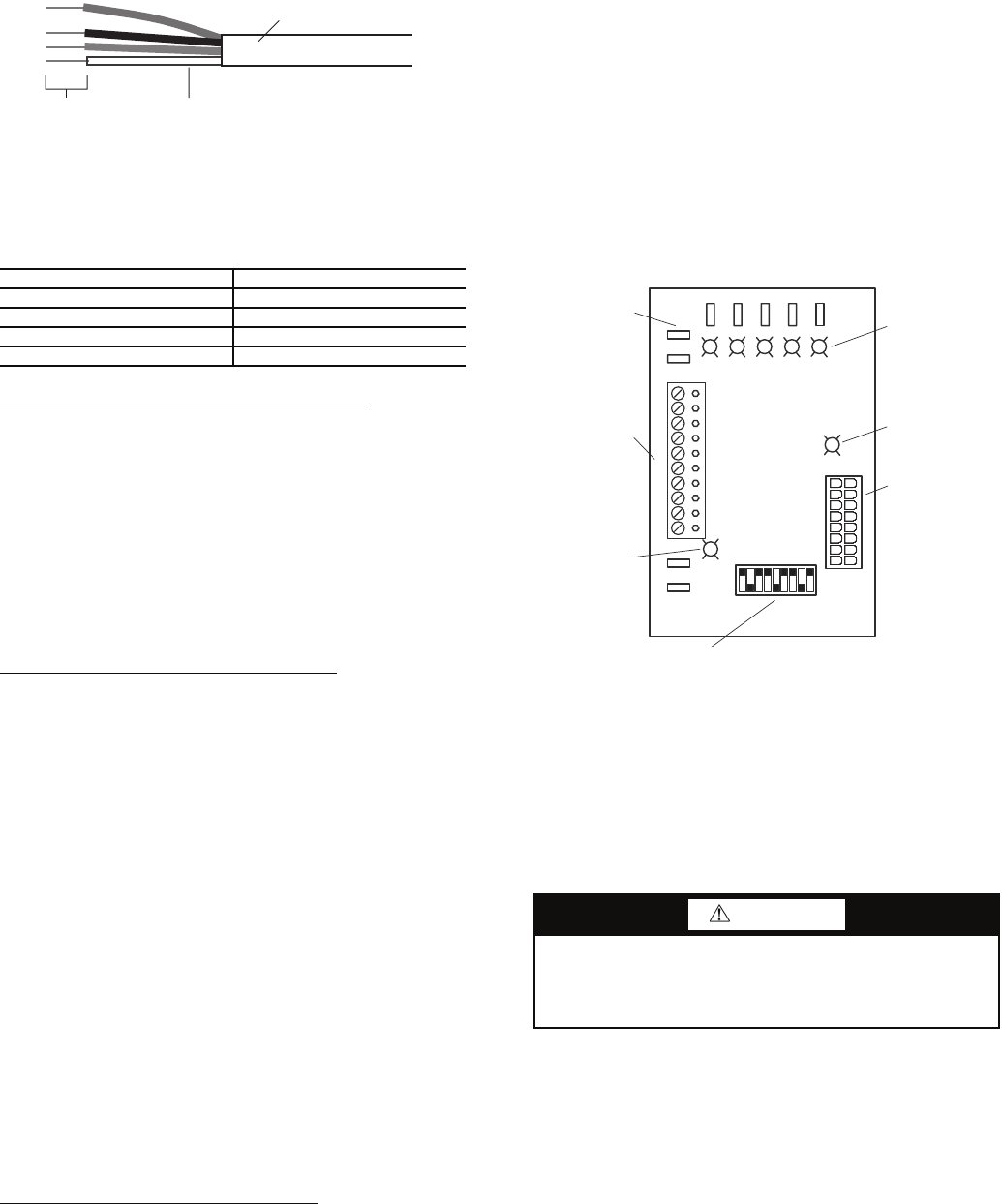
Step 10 — Operate ECM Interface Board —
The ECM fan is controlled by an interface board that converts
thermostat inputs and field selectable cfm settings to signals
used by the ECM (electronically commutated motor)
controller. See Fig. 33.
NOTE: Power must be off to the unit for at least three seconds
before the ECM will recognize a speed change. The motor will
recognize a change in the CFM Adjust or Dehumidification
mode settings while the unit is powered.
There are four different airflow settings from lowest airflow
rate (speed tap 1) to the highest airflow rate (speed tap 4).
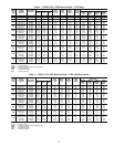
Table 11 indicates settings for both versions of the ECM inter-
face board, followed by detailed information for each setting.
COOLING — The cooling setting determines the cooling
(normal) cfm for all units with ECM motor. Cooling (normal)
setting is used when the unit is not in Dehumidification mode.
Tap 1 is the lowest cfm setting, while tap 4 is the highest cfm
setting. To avoid air coil freeze-up, tap 1 may not be used if the
Dehumidification mode is selected. See Table 11.
HEATING — The heating setting determines the heating cfm
for 50PSH, PSV, PSD units. Tap 1 is the lowest cfm setting,
while tap 4 is the highest cfm setting. See Table 11.
CFM ADJUST — The CFM Adjust setting allows four selec-
tions. The NORM setting is the factory default position. The +
or – settings adjust the airflow by ±15%. The + or – settings are
used to “fine tune” airflow adjustments. The TEST setting runs
the ECM at 70% torque, which causes the motor to operate
like a standard PSC motor, and disables the cfm counter. See
Tables 11-13 for ECM and PSC blower motors performance
data.
WIRE TERMINAL
Red +12-v
Black .Rnet
White Rnet+
Green Gnd
–
CAUTION
When the disconnect switch is closed, high voltage is
present in some areas of the electrical panel. Exercise cau-
tion when working with energized equipment. Failure to
heed this safety precaution could lead to personal injury.
Fig. 32 — Rnet Cable Wire
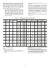
OUTER JACKET
INNER INSULATION
.25 IN.
a50-8443
Y
GGGGR
W
O
Y2
Y1
G
R
C
Y2
Y1
G
O
W
C
R
DH
AL1
A
A
AL1
SW1
SW2
SW3
SW4
SW5
SW6
SW7
SW8
SW9
OFF
ON
G
DEHUM
CFM
TB1
J1
S1
THERMOSTAT
INPUT LEDS
CFM COUNTER
1 FLASH PER 100 CFM
ECM MOTOR
LOW VOLTAGE
CONNECTOR
1/4" SPADE
CONNECTIONS
TO COMPLETE C OR
DELUXE D BOARD
THERMOSTAT
CONNECTIONS
DEHUMIDIFICATION
LED
FAN SPEED SELECTION DIP SWITCH
Fig. 33 — ECM Interface Board Physical Layout
A50-7739