


19
Thermistor
Ground
Wire Nut
Relay Contacts - N.C.
Relay Contacts - N.O.
Low Pressure Switch
High Pressure Switch
Splice Cap
Circuit Breaker
Capacitor
LED
G
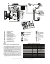
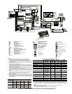
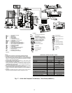
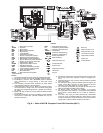
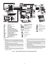
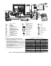
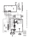
NOTES:
1. Compressor and blower motor thermally protected internally.
2. All wiring to the unit must comply with NEC and local codes.
3. 208-240 60 Hz units are wired for 208v operation. Transformer is energy
limiting or may have circuit breaker.
4. FP1 thermistor provides low temperature protection for water. When
using antifreeze solutions, cut JW3 jumper.
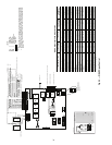
5. Refer to multiple protocol controller (MPC), LON, or TSTAT Installation,
Application, and Operation Manual for control wiring to the wire from
PremierLink controller to “Y” Complete C when motorized valve is not
used. Thermostat wiring must be “Class 1” and voltage rating equal to or
greater than unit supply voltage.
6. 24v alarm signal shown. For dry contact, cut JW1 jumper and dry con-
tact will be available between AL1 and AL2.
7. Transformer secondary ground via green wire with yellow stripe from “C”
terminal to control box.
8. Aquastat is supplied with unit and must be wired in series with the hot
leg to the pump. Aquastat is rated for voltages up to 277v.
LEGEND
*Optional Wiring.
AL — Alarm Relay Contacts
ASTAT — Aquastat
BM — Blower Motor
BR — Blower Relay
CB — Circuit Breaker
CC — Compressor Contactor
CO — Sensor, Condensate Overflow
CR — Cooling Relay
DTS — Discharge Temp Switch
ECM — Electronically Commuted Motor
FP1 — Sensor, Water Coil Freeze Protection
FP2 — Sensor, Air Coil Freeze Protection
HP — High Pressure Switch
HPWS — High Pressure Water Switch
HWG — Hot Water Generator
JW — Jumper Wire
LOC — Loss of Charge Pressure Switch
LWT — Leaving Water Temperature
MV — Motorized Valve
MVES — Motorized Valve End Switch
P1 — Field Wiring Terminal Block
RVS — Reversing Valve Solenoid
SAT — Saturated Air Temperature
TRANS — Transformer
UPS — Unit Performance Sentinel
Field Line Voltage Wiring
Field Low Voltage Wiring
Field Line Voltage Wiring
Field Low Voltage Wiring
Printed Circuit Trace
Optional Wiring
Relay/Contactor Coil
Condensate Pan
Solenoid Coil
Temperature Switch
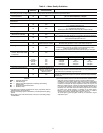
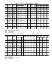
COMPLETE C CONTROLLER FAULT CODES
DESCRIPTION OF OPERATION LED ALARM RELAY
Normal Mode ON Open
Normal Mode with UPS Warning ON
Cycle (Closed 5 Sec.
Open 25 Sec.)
Complete C is Non-Functional OFF Open
Fault Retry Slow Flash Open
Lockout Fast Flash Closed
Over/Under Voltage Shutdown Slow Flash Open (Closed After 15 Min.)
Test Mode-No Fault in Memory Flashing Code 1 Cycling Code 1
Test Mode-HP Fault in Memory Flashing Code 2 Cycling Code 2
Test Mode-LP Fault in Memory Flashing Code 3 Cycling Code 3
Test Mode-FP1 Fault in Memory Flashing Code 4 Cycling Code 4
Test Mode-FP2 Fault in Memory Flashing Code 5 Cycling Code 5
Test Mode-CO Fault in Memory Flashing Code 6 Cycling Code 6
Test Mode-Over/Under Shutdown
in Memory
Flashing Code 7 Cycling Code 7
Test Mode-UPS in Memory Flashing Code 8 Cycling Code 8
Swapped FP1/FP2 Lockout Flashing Code 9 Cycling Code 9
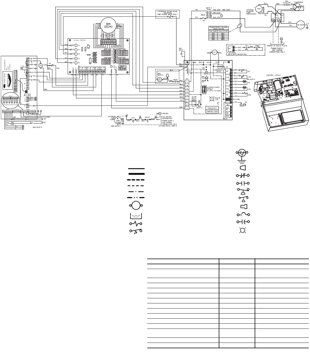
a50-8232
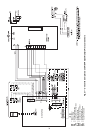
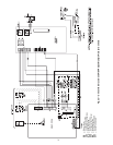
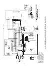
Fig. 20 — Units with Complete C and Premierlink™ Controller, Single-Phase (208/230 V)