


30
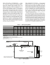
DEHUMIDIFICATION MODE — The dehumidification mode
setting provides field selection of humidity control. When oper-
ating in the normal mode, the cooling airflow settings are deter-
mined by the cooling tap setting in Table 11. When dehumidifi-
cation is enabled, there is a reduction in airflow in cooling to in-
crease the moisture removal of the heat pump. The
Dehumidification mode can be enabled in two ways:
1. Constant Dehumidification mode: When the Dehumidifi-
cation mode is selected via DIP switch, the ECM will
operate with a multiplier applied to the cooling CFM
settings (approximately 20 to 25% lower airflow). Any
time the unit is running in the Cooling mode, it will oper-
ate at the lower airflow to improve latent capacity. The
“DEHUM” LED will be illuminated at all times. Heating
airflow is not affected.
NOTE: Do not select Dehumidification mode if cooling
setting is tap 1.
2. Automatic (humidistat-controlled) Dehumidification
mode: When the Dehumidification mode is selected
via DIP switch AND a humidistat is connected to termi-
nal DH, the cooling airflow will only be reduced when
the humidistat senses that additional dehumidification is
required. The DH terminal is reverse logic. Therefore,
a humidistat (not dehumidistat) is required. The
“DEHUM” LED will be illuminated only when the humi-
distat is calling for Dehumidification mode. Heating
airflow is not affected.
NOTE: Do not select Dehumidification mode if cooling
setting is tap 1.
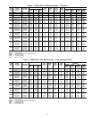
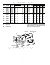
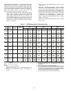
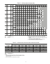
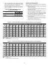
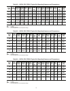
Table 11 — ECM Blower Motor Performance Data
LEGEND
NOTES:
1. Factory setting is Tap Setting 2.
2. Airflow is controlled within 5% up to the Max ESP shown with
wet coil.
3. Do not select Dehumidification mode if Tap Setting is on
Setting 1.
4. All units are ARI/ISO (Air Conditioning & Refrigeration Institute/
International Organization for Standardization) 13256-1 rated
Tap Setting 3.
5. Airflow in cfm with wet coil and clean air filter.
6. Units have an ECM (electronically commuted motor) fan motor
as a standard feature. The small additional pressure drop of
the reheat coil causes the ECM motor to slightly increase rpm
to overcome the added pressure drop and maintain selected
cfm up to maximum ESP (external static pressure).
7. Unit sizes 006-012 are not available with ECM motors.
50PS
UNIT
SIZE
MAX
ESP
(in. wg)
FAN
MOTOR
(hp)
TAP
SETTING
COOLING MODE
(cfm)
DEHUMIDIFICATION MODE
(cfm)
HEATING MODE
(cfm)
Stage 1 Stage 2 Fan Stage 1 Stage 2 Fan Stage 1 Stage 2 Fan
018 0.50
1
/
2
4 750 620 380 590 480 380 750 620 380
3 700 570 350 550 450 350 700 570 350
2 620 510 310 480 400 310 620 510 310
1 530 430 270 — — — 530 430 270
024 0.50
1
/
2
4 950 780 470 740 610 470 1060 870 470
3 850 700 420 660 540 420 950 780 420
2 730 600 360 570 470 360 820 670 360
1 610 500 300 — — — 690 570 300
030 0.50
1
/
2
4 1130 920 560 880 720 560 1230 1000 560
3 1000 820 500 780 640 500 1100 900 500
2 880 720 440 680 560 440 980 800 440
1 750 620 380 — — — 850 700 380
036 0.50
1
/
2
4 1400 1150 700 1090 900 700 1400 1150 700
3 1250 1020 630 980 800 630 1250 1020 630
2 1080 890 540 840 690 540 1080 890 540
1 900 740 450 — — — 900 740 450
042 0.50
1
/
2
4 1580 1290 790 1230 1010 790 1580 1290 790
3 1400 1150 700 1100 900 700 1400 1150 700
2 1230 1000 610 960 790 610 1230 1000 610
1 1050 860 530 — — — 1050 860 530
048 0.75 1
4 1730 1420 870 1350 1110 870 1850 1520 870
3 1550 1270 780 1210 990 780 1650 1350 780
2 1330 1090 670 1040 850 670 1430 1180 670
1 1120 920 560 — — — 1200 980 560
060 0.75 1
4 2050 1680 1030 1600 1310 1030 2280 1870 1030
3 1825 1500 910 1420 1170 910 2050 1680 910
2 1580 1300 790 1230 1010 790 1750 1430 790
1 1320 1080 660 — — — 1470 1210 660
070 0.75 1
4 2230 1780 1100 1710 1400 1100 2230 1780 1100
3 1950 1600 980 1520 1250 980 2100 1680 980
2 1700 1400 850 1330 1090 850 1840 1470 850
1 1450 1200 730 — — — 1520 1220 730
ESP — External Static Pressure