


18
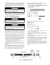
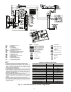
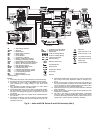
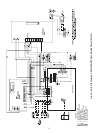
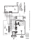
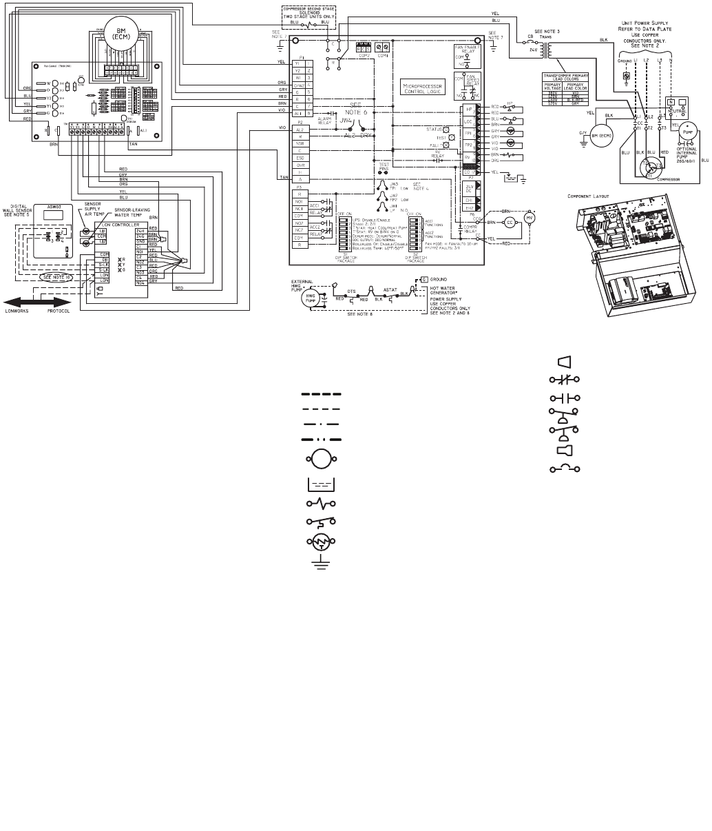
NOTES:
1. Compressor and blower motor thermally protected internally.
2. All wiring to the unit must comply with NEC and local codes.
3. Transformer is wired to 460 v (BLK/RED) lead for 460/3/60
units. Transformer is energy limiting or may have circuit
breaker.
4. FP1 thermistor provides freeze protection for water. When
using antifreeze solutions, cut JW3 jumper.
5. Typical thermostat wiring shown. Refer to thermostat installa-
tion instructions for wiring to the unit. Thermostat wiring must
be Class 1 and voltage rating equal to or greater than unit sup-
ply voltage.
6. Factory cut JW1 jumper. Dry contact will be available between
AL1 and AL2.
7. Transformer secondary ground via Deluxe D board standoffs
and screws to control box. (Ground available from top two
standoffs as shown.)
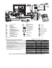
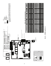
LEGEND
AL — Alarm Relay Contacts
ASTAT — Aquastat
BM — Blower Motor
BMC — Blower Motor Capacitor
BR — Blower Relay
CB — Circuit Breaker
CC — Compressor Contactor
CO — Sensor, Condensate Overflow
DTS — Discharge Temperature Switch
ECM — Electronically Commutated Motor
FP1 — Sensor, Water Coil Freeze Protection
FP2 — Sensor, Air Coil Freeze Protection
HP — High-Pressure Switch
HPWS — High-Pressure Water Switch
HWG — Hot Water Generator
JW1 — Clippable Field Selection Jumper
LOC — Loss of Charge Pressure Switch
LON — Local Operating Network
MV — Motorized Valve
NEC — National Electrical Code
*Optional Wiring.
P1 — Field Wiring Terminal Block
RVS — Reversing Valve Solenoid
TRANS — Transformer
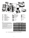
Field Line Voltage Wiring
Field Low Voltage Wiring
Printed Circuit Trace
Optional Wiring
Relay/Contactor Coil
Condensate Pan
Solenoid Coil
Temperature Switch
Thermistor
Ground
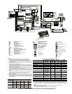
8. Aquastat is supplied with unit and must be wired in series with
the hot leg to the pump. Aquastat is rated for voltages up to
277-v.
9. Blower motor is factory wired for medium and high speeds. For
any other combination of speeds, at the motor attach the BLK
wire to the higher of the two desired speed taps and the BLU
wire to the lower of the two desired speed taps.
10. Optional LON wires. Only connect if LON connection is desired
at the wall sensor.
11. Blower motor is factory wired for high and low speeds. No other
combination is available.
12. The 460-v units using an ECM (electronically commutated
motor) fan motor, modulating HWR (hot water reheat), and/or
an internal secondary pump will require a neutral wire from the
supply side in order to feed the accessory with 265-v.
Wire Nut
Relay Contacts - N.C.
Relay Contacts - N.O.
Low Pressure Switch
High Pressure Switch
Splice Cap
Circuit Breaker
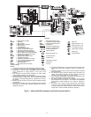
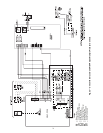
Deluxe D
HP
LOC
FP1
FP2
RVS
CO
SEE NOTE 4
a50-8364
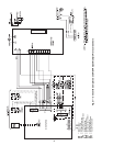
Fig 19 — Units with ECM, Deluxe D and LON Controller (460 V)