


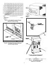

Route thermostat cable or equivalent single leads of col-
ored wire from subbase terminals to low-voltage connec-
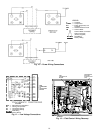
tions on unit (shown in Fig. 11) as described in Steps1-4
below.
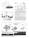
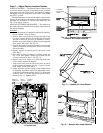
1. If unit is mounted on roof curb and accessory thru-the-
curb service plate connection is used, route wire through
connection plate.
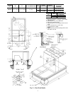
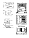
2. Pass control wires through the hole provided on unit
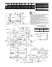
(see connection D in Connection Sizes table in Fig. 7).
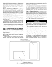
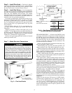
3. Feed wires through the raceway built into the corner post
to the 24-v barrier located on the left side of the control
box. See Fig. 12. The raceway provides the UL-required
(Underwriters’Laboratories) clearance between high- and
low-voltage wiring.
4. Connect thermostat wires to screw terminals on low-
voltage connection board.
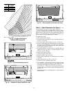
HEAT ANTICIPATOR SETTINGS — Set heat anticipator
settings at .14 amp for the first stage and .20 amp for second-
stage heating.
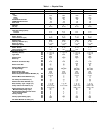
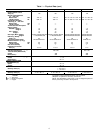
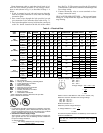
Table 2 — Electrical Data
UNIT
48TJ
NOMINAL
VOLTAGE
(60 Hz)
IFM
TYPE
VOLTAGE
RANGE
COMPR
(ea)
OFM
(ea)
IFM
COMBUSTION
FAN MOTOR
POWER SUPPLY
DISCONNECT
SIZE*
Min Max RLA LRA Hp FLA FLA FLA MCA MOCP† FLA LRA
008
(7
1
⁄
2
Tons)
208/230
(3 phase)
Std 187 254 13.6 73.4
1
⁄
4
1.4 5.8 .57 39.2/39.2 45/45 41/41 194/194
460
(3 phase)
Std 414 508 6.2 37.7
1
⁄
4
0.8 2.6 .30 18.0 25 19 99
575
(3 phase)
Std 518 632 4.9 31.0
1
⁄
4
0.8 2.6 .30 14.2 20 15 81
009
(8
1
⁄
2
Tons)
208/230
(3 phase)
Std 187 254 15.8 92.0
1
⁄
4
1.4 5.8 .57 44.2/44.2 50/50 46/46 231/231
460
(3 phase)
Std 414 508 7.4 46.0
1
⁄
4
0.8 2.6 .30 20.7 25 22 116
575
(3 phase)
Std 518 632 5.9 44.0
1
⁄
4
0.8 2.6 .30 16.5 20 17 107
012
(10 Tons)
208/230
(3 phase)
Std
187 254 17.9 110.0
1
⁄
4
1.4
5.8
.57
48.9/48.9 60/60 51/51 267/267
Alt 7.5 50.6/50.6 60/60 53/53 286/286
460
(3 phase)
Std
414 508 8.6 55.0
1
⁄
4
0.8
2.6
.30
23.4 30 24 134
Alt 3.4 24.2 30 25 173
575
(3 phase)
Std
518 632 6.4 44.0
1
⁄
4
0.8
2.6
.30
17.6 20 18 107
Alt 3.4 18.2 20 19 139
014
(12
1
⁄
2
Tons)
208/230
(3 phase)
Std
187 254 23.0 146.0
1
⁄
4
1.4
10.6
.57
65.2/65.2 80/80 68/68 383/383
Alt 15.0 69.6/69.6 80/80 73/73 406/406
460
(3 phase)
Std
414 508 10.4 73.0
1
⁄
4
0.8
4.8
.30
29.6 35 31 192
Alt 7.4 32.2 35 34 203
575
(3 phase)
Std
518 632 8.3 58.4
1
⁄
4
0.8
4.8
.30
23.6 30 25 154
Alt 7.4 25.7 35 27 163
LEGEND
FLA — Full Load Amps
HACR — Heating, Air Conditioning and Refrigeration
IFM — Indoor (Evaporator) Fan Motor
LRA — Locked Rotor Amps
MCA — Minimum Circuit Amps
MOCP — Maximum Overcurrent Protection
NEC — National Electrical Code
OFM — Outdoor (Condenser) Fan Motor
RLA — Rated Load Amps
UL — Underwriters’ Laboratories
*Used to determine minimum disconnect size per NEC.
†Fuse or HACR circuit breaker.
NOTES:
1. In compliance with NEC requirements for multimotor and combi-
nation load equipment (refer to NEC Articles 430 and 440), the
overcurrent protective device for the unit shall be fuse or HACR
breaker. Canadian units may be fuse or circuit breaker.
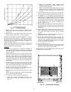
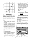
2. Unbalanced 3-Phase Supply Voltage
Never operate a motor where a phase imbalance in supply volt-
age is greater than 2%.
Use the following formula to determine
the percent voltage imbalance.
% Voltage Imbalance
max voltage deviation from average voltage
= 100 x
average voltage
EXAMPLE: Supply voltage is 460-3-60.
AB = 452 v
BC = 464 v
AC = 455 v
452 + 464 + 455
Average Voltage =
3
1371
=
3
= 457
NOTE: The 575-v 48TJ008-014 units are UL, Canada, only.
Determine maximum deviation from average voltage.
(AB) 457 - 452=5v
(BC) 464 - 457=7v
(AC) 457 - 455=2v
Maximum deviation is 7 v.
Determine percent voltage imbalance.
7
% Voltage Imbalance = 100 x
457
= 1.53%
This amount of phase imbalance is satisfactory as it is below the
maximum allowable 2%.
IMPORTANT: If the supply voltage phase imbalance is
more than 2%, contact your local electric utility company
immediately.
9