


Flue Gas Passageways — To inspect the flue col-
lector box and upper areas of the heat exchanger:
1. Remove the combustion blower wheel and motor assem-
bly according to directions in Combustion-Air Blower sec-
tion below.
2. Remove the flue cover to inspect the heat exchanger.
3. Clean all surfaces as required using a wire brush.
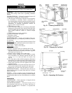
Combustion-Air Blower — Clean periodically to as-
sure proper airflow and heating efficiency. Inspect blower
wheel every fall and periodically during heating season. For
the first heating season, inspect blower wheel bimonthly to
determine proper cleaning frequency.
To inspect blower wheel, shine a flashlight into drafthood
opening. If cleaning is required, remove motor and wheel as
follows:
1. Slide burner access panel out.
2. Remove the 6 screws that attach induced-draft motor hous-
ing to vestibule plate (Fig. 45).
3. The blower wheel can be cleaned at this point. If
additional cleaning is required, continue with Steps 4
and 5.
4. To remove blower from the motor shaft, remove 2
setscrews.
5. To remove motor, remove the 4 screws that hold blower
housing to mounting plate. Remove the motor cooling fan
by removing one setscrew. Then remove nuts that hold
motor to mounting plate.
6. To reinstall, reverse the procedure outlined above.
Limit Switch — Remove blower access panel (Fig. 7).
Limit switch is located on the fan deck.
Burner Ignition — Unit is equipped with a direct spark
ignition 100% lockout system. Integrated Gas Unit Control-
ler (IGC) is located in the control box (Fig. 12). Module con-
tains a self-diagnostic LED. A single LED on the IGC pro-
vides a visual display of operational or sequential problems
when the power supply is interrupted. When a break in power
occurs, the module will be reset (resulting in a loss of fault
history) and the indoor (evaporator) fan ON/OFF times will
be reset. For additional information, refer to the Start-Up,
Heating section on page 23. The LED error code can be ob-
served through the viewport. See Fig. 12. During servicing
refer to the label on the control box cover or Table 16 for an
explanation of LED error code descriptions.
If lockout occurs, unit may be adjusted by interrupting power
supply to unit for at least 5 seconds.
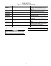
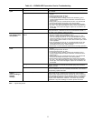
Table 16 — LED Error Code Description*
LED INDICATION ERROR CODE DESCRIPTION
ON Normal Operation
OFF Hardware Failure
1 Flash† Evaporator Fan On/Off Delay Modified
2 Flashes Limit Switch Fault
3 Flashes Flame Sense Fault
4 Flashes 4 Consecutive Limit Switch Faults
5 Flashes Ignition Lockout Fault
6 Flashes Induced-Draft Motor Fault
7 Flashes Rollout Switch Fault
8 Flashes Internal Control Fault
LED — Light-Emitting Diode
*A 3-second pause exists between LED error code flashes. If more
than one error code exists, all applicable codes will be displayed in
numerical sequence.
†Indicates a code that is not an error. The unit will continue to op-
erate when this code is displayed.
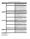
IMPORTANT: Refer to Troubleshooting Tables 17-21 for additional
information.
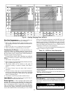
Main Burners — At the beginning of each heating sea-
son, inspect for deterioration or blockage due to corrosion or
other causes. Observe the main burner flames and adjust if
necessary.
When working on gas train, do not hit or plug orifice
spuds.
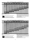
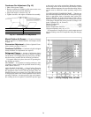
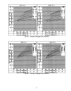
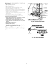
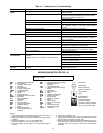
Fig. 44 — Cooling Charging Chart; 48TJ014
28