


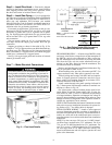

Locate mechanical draft system flue assembly at least
48 in. from any opening through which combustion prod-
ucts could enter the building, and at least 48 in. from an ad-
jacent building or combustible material. When unit is located
adjacent to public walkways, flue assembly must be at least
7 ft above grade.
Flue vent discharge must have a minimum horizontal clear-
ance of 48 in. from electric and gas meters, gas regulators,
and gas relief equipment.
Flue gas can deteriorate building materials. Orient unit so
that flue gas will not affect building materials.
Adequate combustion-air space must be provided for proper
operation of this equipment. Be sure that installation com-
plies with all local codes and Section 5.3, Air for Combus-
tion and Ventilation, NFGC (National Fuel Gas Code), ANSI
(American National Standards Institute) Z223.1-latest year
and addendum Z223.1A-latest year. In Canada, installation
must be in accordance with the CAN1. B149.1 and
CAN1.B149.2 installation codes for gas burning appliances.
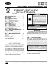
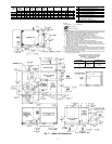
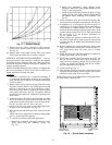
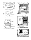
MAXIMUM ALLOWABLE
DIFFERENCE (in.)
A-B B-C A-C
0.5 1.0 1.0
Fig. 3 — Unit Leveling Tolerances
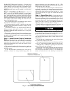
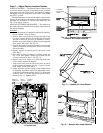
NOTE: Drain plug is shown in factory-installed position.
Fig. 4 — Condensate Drain Pan
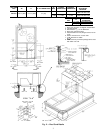
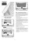
NOTES:
1. Dimension in ( ) is in millimeters.
2. Hook rigging shackles through holes in base rail as shown in detail ‘‘A.’’
Holesin baserailsare centeredaroundthe unitcenterof gravity.Use wooden
top skid when rigging to prevent rigging straps from damaging unit.
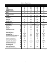
3. Weights include base unit without economizer. See Table 1 for economizer
weights.
All panels must be in place when rigging.
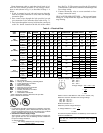
UNIT
MAX
WEIGHT
DIMENSIONS
‘‘A’’ ‘‘B’’ ‘‘C’’
lb kg in. mm in. mm in. mm
48TJD/TJE/TJF008 870 395 87.38 2219 40.25 1022 41.31 1050
48TJD/TJE/TJF009 880 399 87.38 2219 40.25 1022 41.31 1050
48TJD/TJE/TJF012 1035 469 87.38 2219 40.25 1022 49.31 1253
48TJD/TJE014 1050 476 87.38 2219 40.25 1022 49.31 1253
Fig. 6 — Rigging Details
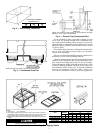
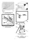
NOTE: Trap should be deep enough to offset maximum unit static
difference. A 4-in. trap is recommended.
Fig. 5 — External Trap Condensate Drain
4