


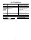
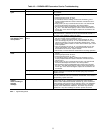


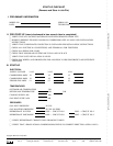

Table 21 — Heating Service Troubleshooting
PROBLEM CAUSE REMEDY
Burners will not
ignite.
Misaligned spark electrodes. Check flame ignition and sensor electrode positioning.
Adjust as needed.
No gas at main burners. Check gas line for air purge as necessary. After purging
gas line of air, allow gas to dissipate for at least 5 min-
utes before attempting to relight unit.
Check gas valve.
Water in gas line. Drain water and install drip leg to trap water.
No power to furnace. Check power supply, fuses, wiring, and circuit breaker.
No 24 v power supply to control circuit. Check transformer. Transformers with internal overcur-
rent protection require a cool down period before
resetting.
Miswired or loose connections Check all wiring and wirenut connections.
Burned-out heat anticipator in thermostat. Replace thermostat.
Broken thermostat wires. Run continuity check. Replace wires, if necessary.
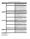
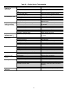
Inadequate heating. Dirty air filter. Clean or replace filter as necessary.
Gas input to unit too low. Check gas pressure at manifold. Clock gas meter for
input. If too low, increase manifold pressure, or replace
with correct orifices.
Unit undersized for application. Replace with proper unit or add additional unit.
Restricted airflow. Clean filter, replace filter, or remove any restrictions.
Blower speed too low. Use high speed tap, increase fan speed, or install op-
tional blower, as suitable for individual units.
Limit switch cycles main burners. Check rotation of blower, thermostat heat anticipator set-
tings, and temperature rise of unit. Adjust as needed.
Too much outdoor air. Adjust minimum position.
Check economizer operation.
Poor flame
characteristics.
Incomplete combustion (lack of combustion air)
results in:
Aldehyde odors, CO, sooting flame, or floating flame.
Check all screws around flue outlets and burner com-
partment. Tighten as necessary.
Cracked heat exchanger.
Overfired unit — reduce input, change orifices, or adjust
gas line or manifold pressure.
Check vent for restriction. Clean as necessary.
Check orifice to burner alignment.
Burners will not
turn off.
Unit is locked into Heating mode for a one minute
minimum.
Wait until mandatory one minute time period has
elapsed or power to unit.
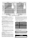
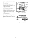
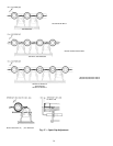
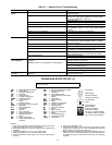
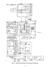
LEGEND AND NOTES FOR FIG. 48
IMPORTANT: Refer to unit wiring label for actual unit
wiring information.
NOTES:
1. If any of the original wire furnished must be replaced, it must be
replaced with type 90 C wire or its equivalent.
2. Three-phase motors are protected under primary single phasing
conditions.
3. Thermostat: HH07AT170, 172, 174 and P272-2783
Subbase: HH93AZ176, 178 and P272-1882, 1883
4. Set heat anticipator for first stage at 0.14 amp, second stage at
0.2 amp.
5. Use copper conductors only.
6. TRAN is wired for 230 v unit. If unit is to be run with 208 v power
supply, disconnect BLK wire from 230 v tap (RED) and connect to
200 v tap (BLU). Insulate end of 230 v tap.
7. When economizerassembly is installed moveGRAwire from con-
nection board (Y1) to GRAwire from PL6,5; move ORN wire from
connection board (Y2) to ORN wire from PL6,9, on economizer
assembly.
AHA — Adjustable Heat Anticipator
BR — Burner Relay
C—Contactor, Compressor
CAP — Capacitor
CB — Circuit Breaker
CC — Cooling Compensator
COMP — Compressor Motor
CR — Control Relay
D—Diode
EC — Enthalpy Control
EPS — Economizer Pressure Switch
EQUIP — Equipment
FPT — Freeze-Protection
Thermostat
GND — Ground
GVR — Gas Valve Relay
HPS — High-Pressure Switch
HS — Hall Effect Sensor
I—Ignitor
IDM — Induced-Draft Motor
IFC — Indoor (Evaporator) Fan
Contactor
IFM — Indoor (Evaporator) Fan Motor
IGC — Integrated Gas Unit
Controller
LED — Light Emitting Diode
LPS — Low-Pressure/Loss-of-Charge
Switch
LS — Limit Switch
MGV — Main Gas Valve
MTR — Motor
OAT — Outdoor Air Thermostat
OFM — Outdoor-Fan Motor
PL — Plug Assembly
QT — Quadruple Terminal
R—Relay
RS — Rollout Switch
SAT — Supply Air Thermostat
SEN — Sensor
TC — Thermostat-Cooling
TH — Thermostat-Heating
TRAN — Transformer
Field Splice
Marked Wire
Terminal (Marked)
Terminal (Unmarked)
Terminal Block
Splice
Splice (Marked)
Factory Wiring
Field Control Wiring
Field Power Wiring
Accessory or Optional Wiring
To indicate common potential
only, not to represent wiring
35